
Valve with fail-safe mechanism

A fail-safe, valve body technology, applied in safety valves, failure prevention, engine cooling, etc.

Active Publication Date: 2016-03-09
HANON SYST EFP DEUT GMBH
View PDF6 Cites 3 Cited by
  • Summary
  • Abstract
  • Description
  • Claims
  • Application Information

AI Technical Summary

Problems solved by technology

However, only in the case of non-self-locking adjusting actuators, the fail-safe mechanism of DE 10 2012 208 652 B3 or its torsion spring always has to perform work relative to the resistance or moment of inertia of the actuator, for which the torsion spring must be correspondingly stiff and thus opposite Earth composition

Method used


Image

  • Valve with fail-safe mechanism
  • Valve with fail-safe mechanism
  • Valve with fail-safe mechanism

Examples


Embodiment Construction

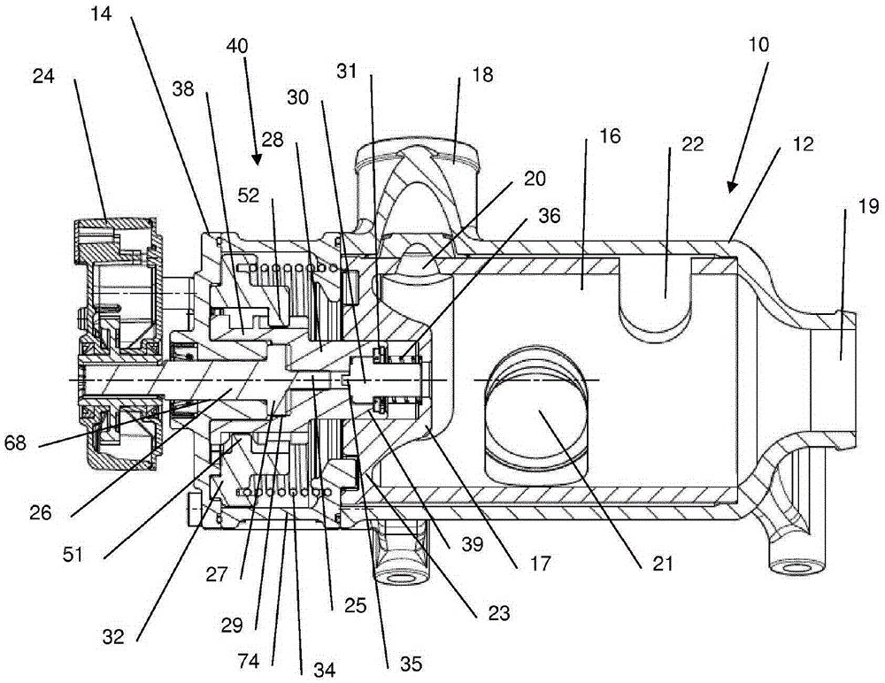
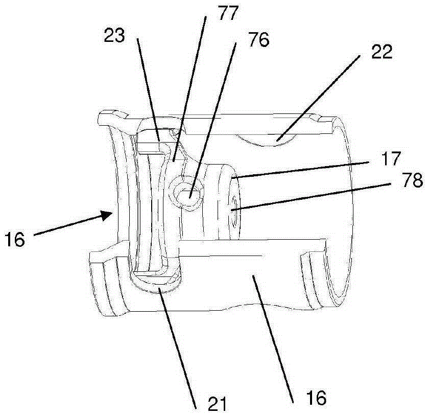
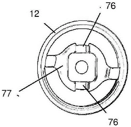
[0031] according to figure 1 , the valve 10 has a substantially hollow-cylindrical housing section 12 with an outlet 19 and a plurality of inlets 18, of which only one, however, is visible. The valve housing 12 rotatably accommodates in its interior a likewise substantially hollow-cylindrical valve body 16 , wherein the valve body 16 has a plurality of inlet channels 20 , 21 , 22 , which according to the The rotational position of the valve body 16 of the respective inlet 18 is aligned such that the coolant flow between the respective inlet 18 and outlet 19 can be varied as a function of the rotational position of the valve body 16 .

[0032] Furthermore, the valve 10 has an adjusting actuator 24 , the shaft 26 of which is indirectly and releasably connected to the valve body 16 for rotating it. In this case, the actuator shaft 26 extends through the opening 68 of the housing cover 14 , which is mounted on a substantially hollow-cylindrical housing body 74 which accommodates ...


PUM


Abstract

Valve (10) for use in a coolant flow, comprising a valve housing (12) with at least one inlet (18) and at least one outlet (19); a valve body (16) which is received rotatably by the valve housing (12), wherein the coolant flow between the inlet (18) and outlet (19) varies depending on the rotary position of the valve body (16); an actuator (24) with a shaft (26) for rotating the valve body (16); and a fail-safe mechanism (40) which can be prestressed rotationally; wherein the valve body (16) is in rotary engagement with an axially movable coupling element (28), via which the valve body (16) is releasably connected indirectly to the actuator shaft (26), wherein, in the case of a fault, the valve body (16) can be decoupled from the actuator shaft (26) as a consequence of an axial movement of the coupling element (28), wherein the fail-safe mechanism (40) is adapted to pass into rotary engagement with the coupling element (28) as a consequence of the axial movement of the coupling element (28), in order to rotate the valve body (16) into a predefined fail-safe position.

Description

technical field [0001] The invention relates to a valve for use in a coolant flow according to the preamble of claim 1 , which is known, for example, from DE 10 2012 208 652 B3. Background technique [0002] Such a valve can be used to control the coolant flow of the internal combustion engine in order to ensure the coolant temperature in the fluid circuit as a function of the load. However, in the event of a fault, for example an incorrect actuation of a valve, a failure of a valve actuator or a valve remaining inserted, an undesired temperature increase of the coolant can result, resulting in an emergency situation which can damage the internal combustion engine. In order to prevent such a fault situation in which the coolant temperature rises in an undesired manner beyond a predetermined temperature, the valve described in DE 10 2012 208 652 B3 has a fail-safe mechanism which, in the event of a fault, causes the valve body to move to a predetermined position in which the...

Claims


Application Information

Patent Timeline
IPC IPC(8): F16K11/085F16K31/00
CPCF16K11/085F16K31/003F01P2031/32F16K17/386F16K31/055
Inventor 弗里德里希·阿施赖特尔汉内斯·霍夫施泰特尔马库斯·奥贝尔阿德施泰特安德烈亚斯·阿维格格尔德·施拉格
Owner HANON SYST EFP DEUT GMBH
Features
  • Generate Ideas
  • Intellectual Property
  • Life Sciences
  • Materials
  • Tech Scout
  • Unparalleled Data Quality
  • Higher Quality Content
  • 60% Fewer Hallucinations
Learn More