
Electrical terminal and method

A terminal, electrical contact technology, applied in the direction of conductive connection, circuit, connection, etc., can solve the problems of inability to screw in the wire, difficult assembly, etc., and achieve the effect of reliable contact, flexible connection scheme, and small operating stroke.

Active Publication Date: 2016-03-16
PHOENIX CONTACT GMBH & CO KG
View PDF11 Cites 0 Cited by
  • Summary
  • Abstract
  • Description
  • Claims
  • Application Information

AI Technical Summary

Problems solved by technology

However, the disadvantage of such screw terminals is that the stripped conductors cannot be easily screwed in directly from above
Especially for larger and solid conductors, this makes assembly difficult, since the conductor has to be bent and inserted axially from the front into the screw terminal before the conductor can be clamped

Method used


Image

  • Electrical terminal and method
  • Electrical terminal and method
  • Electrical terminal and method

Examples


Embodiment Construction

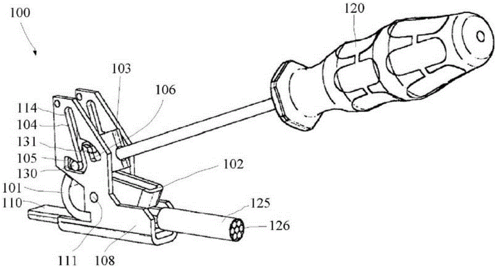
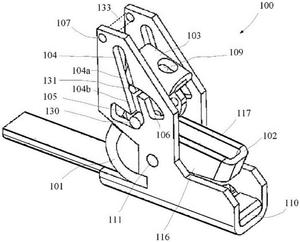
[0043] figure 1 A schematic perspective view of an electrical connection terminal 100 comprising an inserted cable 125 having a plurality of conductors 126 is shown. Here, a tool 120 in the form of a screwdriver is inserted into the lever 103 of the electrical terminal 100 in order to switch the electrical terminal 100 into the clamped state 145 .

[0044] In the clamped state 145 ( Figure 10 ), the clamping rod 102 clamps the inserted conductor 106 towards the current bar 110 . The current bar 110 is accommodated on a support 108 which may be surrounded by a plastic casing not shown in the figures. The connection terminal 100 can be designed as a terminal block.

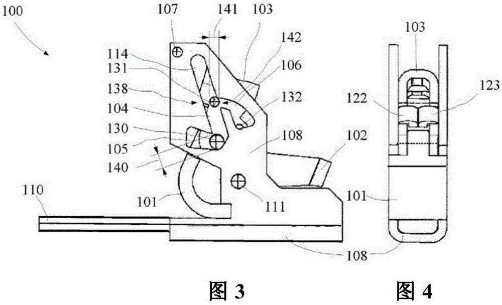
[0045] The clamping lever 102 is rotatably accommodated on the bracket 108 via a shaft 111 . The pin 136 of the clamping spring 101 rests on the shaft 111 (see Figure 7 ).

[0046] Joystick 103 has (see figure 2 ) tool opening 109. A first shaft 130 and a second shaft 131 are arranged on the joystick. Ar...


PUM


Abstract

The invention relates to a terminal (100) for connecting a conductor (126) in an electrically contacting manner to a current bar (110) accommodated on a retainer (108), wherein an actuating lever (103) and a clamping spring (101) are provided. A slotted guide (114) is provided, which comprises a closing slot (104) and a clamping slot (105) branching off transversely from the closing slot. The actuating lever (103) is movably guided in the slotted guide (114) by means of a first pin (130) and a second pin (131).

Description

technical field [0001] The invention relates to an electrical terminal and a method of connecting a wire to a terminal. Background technique [0002] Various terminal blocks suitable for connecting wires of different diameters are known in the prior art. For example, conductors with larger cross-sections can be connected to screw terminals. In this case, the conductor is clamped to the electrical terminal by means of a threaded connection. However, a disadvantage of such screw terminals is that the stripped conductors cannot be easily screwed in directly from above. Especially for larger and solid conductors, this makes assembly more difficult, since the conductor has to be bent and inserted axially from the front into the screw terminal before the conductor can be clamped. [0003] Assembly is easier than with an electrical terminal which enables the wires to be connected to be screwed in from above. In this case, the wires to be connected can be shortened to a suitable...

Claims


Application Information

Patent Timeline
IPC IPC(8): H01R4/50H01R4/52
CPCH01R4/5008H01R4/505H01R4/52
Inventor 安德列亚斯·文特
Owner PHOENIX CONTACT GMBH & CO KG
Learn More