CNC machine tool

A technology of CNC machine tools and clamping mechanism, which is applied to metal processing mechanical parts, clamping, supporting and other directions. It can solve the problems of safety risks for equipment operators, overheating and scrapping of workpieces, equipment failures, etc., and achieve stable and smooth tool changing. The effect of improving work safety and prolonging the service life

Active Publication Date: 2017-12-29
ZHONGSHAN MLTOR CNC TECH CO LTD
View PDF5 Cites 0 Cited by
  • Summary
  • Abstract
  • Description
  • Claims
  • Application Information

AI Technical Summary

Problems solved by technology

The problems existing in the existing technology are: usually only one shape of tool can be clamped for processing at a time, and the tool needs to be replaced manually repeatedly when performing mechanical processing with more complex shapes, which is time-consuming and laborious; However, the tool is exposed relative to the cutter head, which poses safety risks to the equipment itself and the operator; in addition, the existing CNC lathes either do not have a cooling mechanism at all or the cooling mechanism is not set properly, which may easily lead to overheating and scrapping of the workpiece; Moreover, the existing CNC lathes usually do not deal with the cutting chips, and it is easy to cause equipment failure due to the splashing of cutting chips into the joints of various functional components, which poses a great safety hazard

Method used


Image

  • CNC machine tool

Examples


Embodiment Construction

[0017] Below in conjunction with specific embodiment and accompanying drawing, the present invention will be further described:

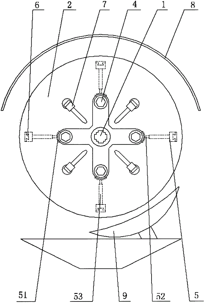
[0018] Refer to attached figure 1 As shown, the CNC machine tool of the present invention includes a workpiece clamping mechanism and a tool clamping mechanism, the workpiece clamping mechanism is provided with a feed drive mechanism, the tool clamping mechanism is provided with a displacement drive mechanism, and the tool clamping mechanism includes a positioning shaft 1, The tool disc 2 is set on the positioning shaft 1, and the tool disc 2 has at least two tool movable grooves, and the cutter 4 is arranged in the tool movable groove along the axial direction of the tool disc; the positioning axis 1 is located at the center of the tool disc 2, and the tool movable groove One end extends to the positioning shaft and the other end extends radially toward the outer edge of the tool disc. There is a tool pushing mechanism 5 for pushing the tool from t...


PUM


Abstract

The invention provides a numerical control machine tool. The numerical control machine tool comprises a workpiece clamping mechanism and a cutter clamping mechanism, wherein the cutter clamping mechanism comprises a positioning shaft, the positioning shaft is sleeved with a cutter disc, at least two cutter movement grooves are formed in the cutter disc, and cutters are arranged in the cutter movement grooves in a penetrating mode in the axial direction of the cutter disc; the positioning shaft is located at the center of the cutter disc, a cuter pushing mechanism used for pushing the cutters to the positioning shaft from the direction away from the positioning shaft is arranged in the cutter movement grooves, the cutter pushing mechanism is provided with a cutter locking / automatic unlocking mechanism, a cutter restoration mechanism used for pulling the cutters to be close to the outer edge of the cutter disc along the cutter movement grooves is arranged in the cutter movement grooves, and the cutter pushing mechanism is provided with a sliding guide rail mechanism and a pushing and sliding driving mechanism; a cutter capturing mechanism is arranged on the positioning shaft. The numerical control machine tool has the advantages that multiple groups of cutters are arranged in the cutter disc in a hidden mode, using is safe, actuating units used for cutter change are reasonably arranged, and cutter change is stable and smooth.

Description

technical field [0001] The invention relates to the field of machining, in particular to a numerically controlled machine tool. Background technique [0002] Existing CNC machine tools generally include a workpiece clamping mechanism and a tool clamping mechanism, the workpiece clamping mechanism is provided with a feed drive mechanism, and the tool clamping mechanism is provided with a displacement drive mechanism. The problems existing in the existing technology are: usually only one shape of tool can be clamped at a time for processing, and the tool needs to be replaced manually repeatedly when performing mechanical processing with more complex shapes, which is time-consuming and laborious; However, the tool is exposed relative to the cutter head, which poses safety risks to the equipment itself and the operator; in addition, the existing CNC lathes either have no cooling mechanism at all or the cooling mechanism is unreasonably set up, which may easily lead to overheatin...

Claims


Application Information

Patent Timeline
Patent Type & Authority Patents(China)
IPC IPC(8): B23Q3/155B23Q11/10B23Q11/08
CPCB23Q3/155B23Q11/08B23Q11/10
Inventor 林守金王君毅邹晓阳杨宏伟钱晓朋李兴强张冬程文发
Owner ZHONGSHAN MLTOR CNC TECH CO LTD
Why Eureka
Try Eureka