A separate automatic rebound horizontal shear locking device

A technology of horizontal shearing and locking devices, which is applied to building components, earthquake resistance, etc., can solve problems such as pipeline breakage and secondary damage, and achieve the effect of preventing vertical deformation

Active Publication Date: 2018-08-07
SHANGHAI UNIV
View PDF7 Cites 0 Cited by
  • Summary
  • Abstract
  • Description
  • Claims
  • Application Information

AI Technical Summary

Problems solved by technology

Seismic isolation can effectively reduce the acceleration seismic response of the nuclear island, but at the same time, the excessive displacement of the seismic isolation layer may cause the pipelines entering and leaving the nuclear island to break, which is likely to cause secondary damage
This has become a key issue limiting the application of seismic isolation technology in nuclear power structures

Method used


Image

  • A separate automatic rebound horizontal shear locking device
  • A separate automatic rebound horizontal shear locking device
  • A separate automatic rebound horizontal shear locking device

Examples


Embodiment 1

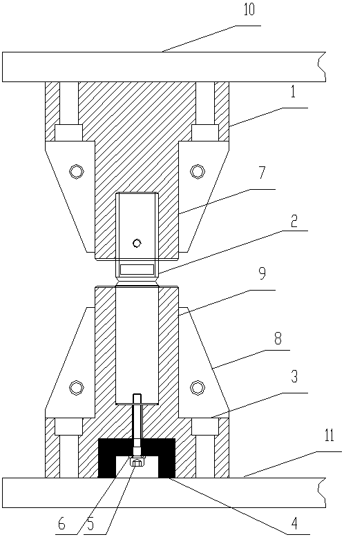
[0034] like figure 1 , Figure 3-Figure 16 As shown, a separate automatic rebound horizontal shear locking device is characterized in that it includes an upper flange 1, a shear pin 2, a lower flange 3, a rubber sleeve 4, a screw 5, a backing plate 6, and an upper sleeve 7. Reinforcing rib 8, lower sleeve 9, upper connecting plate 10, lower connecting plate 11; the upper flange 1, upper sleeve 7 and reinforcing rib 8 are welded together, and connected to the upper part through the upper connecting plate 10 The structure is fixed, the lower flange 3, the lower sleeve 9 and the reinforcing rib 8 are welded together and fixed to the foundation through the lower connecting plate 11; the bottom end of the upper sleeve 7 and the top end of the lower sleeve 9 A round hole is reserved in the center, and the two ends of the shear pin 2 are respectively inserted into the round holes of the upper sleeve 7 and the lower sleeve 9; the lower sleeve 9 and the rubber sleeve 4 are bonded thro...

Embodiment 2

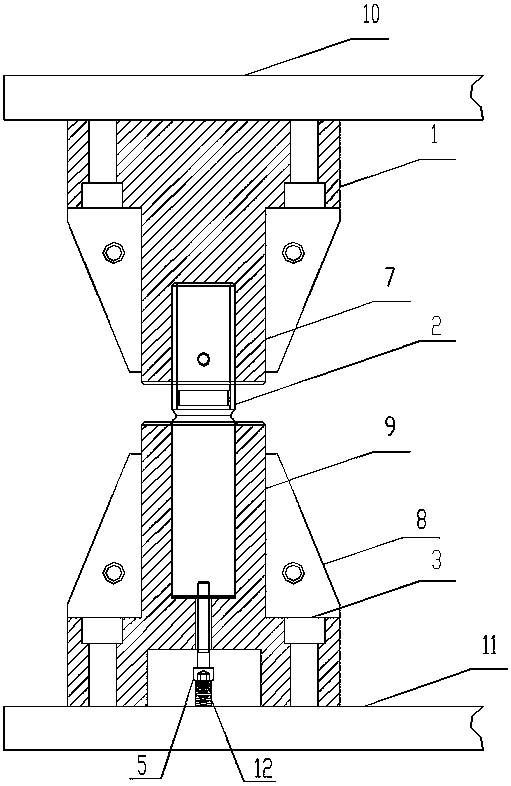
[0037] like Figure 2-Figure 12 As shown, this embodiment is basically the same as Embodiment 1, the difference is that the rubber sleeve 4 and the backing plate 6 are replaced by a spring 12, and after the spring 12 is stretched, one end is connected to the screw 5, and the other end is connected to the lower connecting plate 11 , so that the spring 12 generates a pre-tension force after the screw 5 is tightened, so that the lower half of the shear pin 2 can rebound downward after being cut off, without affecting the normal hysteresis of the rubber bearing.

[0038] This horizontal shear lock is used in conjunction with rubber isolator mounts. The rubber shock-isolation bearing is fixed to the upper structure through the upper connecting plate 10, and fixed to the foundation through the lower connecting plate 11, and bears the vertical force of the upper structure. The upper connecting plate 10 and the lower connecting plate 11 produce a horizontal displacement under the act...


PUM


Abstract

The invention relates to a separated automatic-rebounding horizontal shearing locking device which comprises an upper flange, a shearing pin, a lower flange, a rubber sleeve, a screw, a base plate, an upper sleeve, reinforcing ribs, a lower sleeve, an upper connecting plate and a lower connecting plate. The upper flange, the upper sleeve and the corresponding reinforcing ribs are welded and combined together and are fixed with an upper structure through the upper connecting plate, and the lower flange, the lower sleeve and the corresponding reinforcing ribs are welded and combined together, and are fixed with a foundation through the lower connecting plate. Round holes are reserved in the center of the bottom end of the upper sleeve and the center of the top end of the lower sleeve, and the two ends of the shearing pin are inserted into the round hole of the upper sleeve and the round hole of the lower sleeve respectively. The lower sleeve and a rubber sleeve are bound through a vulcanization technology, the base plate is inserted into the rubber sleeve and the lower sleeve through the screw, and fixed into the shearing pin, the rubber sleeve generates pretension force after the screw is tightened, and therefore the aims that the lower half portion of the shearing pin rebounds downwards after the shearing pin is shorn, and normal hysteresis of a rubber support is not influenced are achieved.

Description

technical field [0001] The invention belongs to the field of shock absorption and isolation of building structures, in particular to a separate automatic rebound horizontal shear locking device. Background technique [0002] The nuclear power plant structure is a special structural system, and earthquake is one of the biggest threats to its safety. When subjected to an earthquake, all structures, systems, components and equipment of a nuclear power plant are excited almost simultaneously, which will endanger the integrity of the structure and the integrity of the functions of the equipment and components. [0003] The loss of life and property caused by the severe earthquake is shocking. If a severe earthquake occurs in the area where the nuclear power plant is located, the consequences will be disastrous. In 1999, the Jiji Earthquake shut down two units of the Taiwan No. 1 Nuclear Power Plant. In 2007, the Niigata Earthquake in Japan led to the closure of the Kashiwazaki K...

Claims


Application Information

Patent Timeline
Patent Type & Authority Patents(China)
IPC IPC(8): E04B1/98
CPCE04B1/98
Inventor 刘文光孔令祥何文福秦川冉茂来
Owner SHANGHAI UNIV
Why Eureka
Try Eureka