An electric pinch valve

A pinch valve, electric technology, applied to valve details, diaphragm valves, valve devices, etc., can solve problems such as inconvenient installation, loud on-off noise, and small clamping force

Active Publication Date: 2018-05-04
INST OF ELECTRICAL ENG CHINESE ACAD OF SCI
View PDF7 Cites 0 Cited by
  • Summary
  • Abstract
  • Description
  • Claims
  • Application Information

AI Technical Summary

Problems solved by technology

[0004] The purpose of the present invention is to overcome the disadvantages of low clamping force, large on-off noise and inconvenient installation in the prior art, and propose a motor-driven pinch valve

Method used


Image

  • An electric pinch valve
  • An electric pinch valve
  • An electric pinch valve

Examples


Embodiment Construction

[0018] The present invention will be further described below in conjunction with the accompanying drawings and specific embodiments.

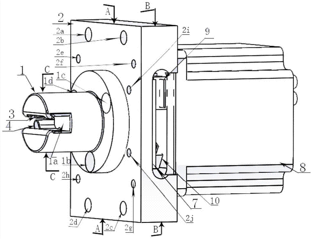
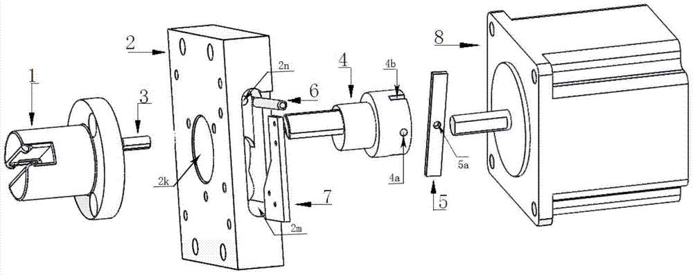
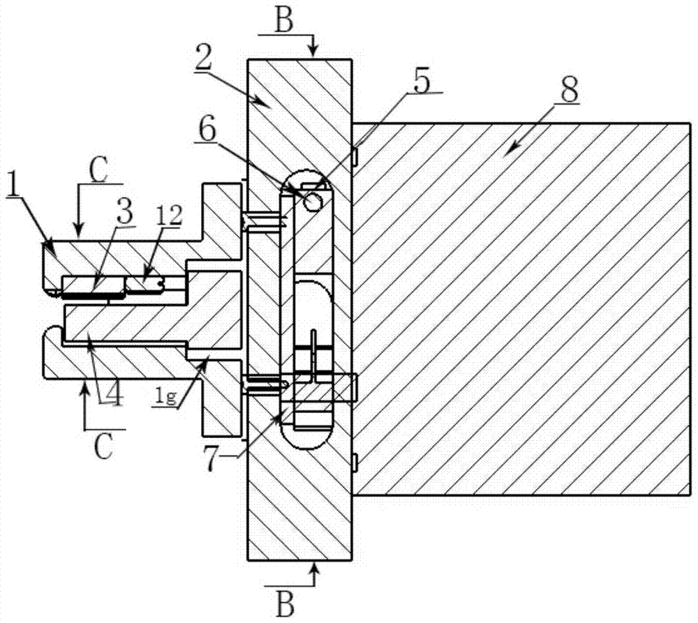
[0019] The electric pinch valve of the present invention includes a hose clamp assembly, a movable valve assembly, a limiting device assembly and a connecting plate 2 . The connecting plate 2 is an intermediate device of the hose clamp assembly, the movable valve assembly, and the limit device assembly. The hose clamp assembly is installed at the front center of the connecting plate 2, and the movable valve assembly is inserted into the central circular hole 2k on the back of the connecting plate 2 and fixed on the back of the connecting plate 2. The limiting device assembly is embedded in the oval cavity 2m on the right side of the connecting plate 2 .

[0020] The hose clamp assembly includes a clamp housing 1 , a retaining post 3 and a second jacking wire 12 . Such as figure 1 As shown, the front end surface of the chuck housing 1 is prov...


PUM


Abstract

The invention relates to an electric pinch valve. A stepping motor rotates forwardly and reversely to drive the pinch valve to be opened and closed, so that the pinch valve can loosen or clamp an elastic hose, thereby controlling the on-off state of the fluid in the elastic hose. The electric pinch valve comprises a hose clamp port assembly, a movable valve assembly, a stopping device assembly and a connecting plate (2), wherein the hose clamp port assembly is installed in the central position of the front surface of the connecting plate (2); the movable valve assembly is inserted into a central circular hole (2k) on the back surface of the connecting plate (2) and fixed to the back surface of the connecting plate (2); the stopping device assembly is inserted into an elliptical cavity (2m) on the right side surface of the connecting plate (2); a rotor (4) and a rotor plate (5) of the movable valve assembly are fixed to a motor rotating shaft and rotate coaxially; two microswitches (9, 10) installed on a switch plate (7) in the stopping device assembly are used for judging to clamp or loosen the hose; and the judgment result is used as the reference for stopping the motor. The electric pinch valve is applicable to biological artificial livers, blood cleansing machines, peritoneal dialysis machines and other medical facilities.

Description

technical field [0001] The invention relates to an electric pinch valve. Background technique [0002] When using blood purification machines, bioartificial liver and other dialysis equipment to treat patients with kidney failure or liver failure, the dialysis machine pumps blood into the equipment pipeline through the patient's vascular access, and the blood needs to be reinfused after purification back into the patient. Its purification process mainly utilizes the intermembrane pressure of the dialyzer to achieve diffusion and convection, remove toxins and excess water molecules in the patient's body, and maintain water, electrolyte, and acid-base balance. During the whole treatment process, the membrane may be damaged due to the pressure on the surface of the membrane exceeding the withstand pressure, causing blood leakage, that is, bleeding, which endangers the life of the patient. In addition, when the purified blood is reinfused back into the patient's body, there ma...

Claims


Application Information

Patent Timeline
Patent Type & Authority Patents(China)
IPC IPC(8): F16K7/04F16K31/04
CPCF16K7/04F16K31/04
Inventor 李柯吴昌哲李明霍小林
Owner INST OF ELECTRICAL ENG CHINESE ACAD OF SCI
Why Eureka
Try Eureka