Telegraph pole for environment monitoring

A technology for utility poles and monitoring the environment, applied in soil material testing, building types, material inspection products, etc., can solve the problems of inability to guarantee long-term protection of equipment, low illegal costs, evasion, etc., and achieve long-term effective and accurate environmental monitoring. Effect

Active Publication Date: 2016-04-27
STATE GRID ZHEJIANG LANXI POWER SUPPLY +2
View PDF6 Cites 5 Cited by
  • Summary
  • Abstract
  • Description
  • Claims
  • Application Information

AI Technical Summary

Problems solved by technology

[0004] The idea of ​​the existing technology is quite good, but there are still many problems. First of all, the installation of the soil moisture monitoring device is a problem. It is acceptable to install such a device in the field, but it is impossible to actually install such a device in the city.
In addition, if such a device is simply installed, both the power supply wiring and the protection of the equipment are problems. A few naughty children may damage a whole set of equipment, and the PVC pipes under the ground cannot guarantee long-term protection of the equipment.
[0005] In addition, in some factory-intensive parks, if an enterprise fails to discharge pollutants in accordance with the regulations, even if it is detected by the monitoring devices of the existing technology, it will be difficult to locate the actual culprit, and it may still cause all parties to shirk when determining responsibility , making it difficult for law enforcement agencies to judge
What's more, some unscrupulous companies even hire people to destroy environmental monitoring equipment, and the cost of breaking the law is very low

Method used


Image

  • Telegraph pole for environment monitoring
  • Telegraph pole for environment monitoring

Examples


Embodiment Construction

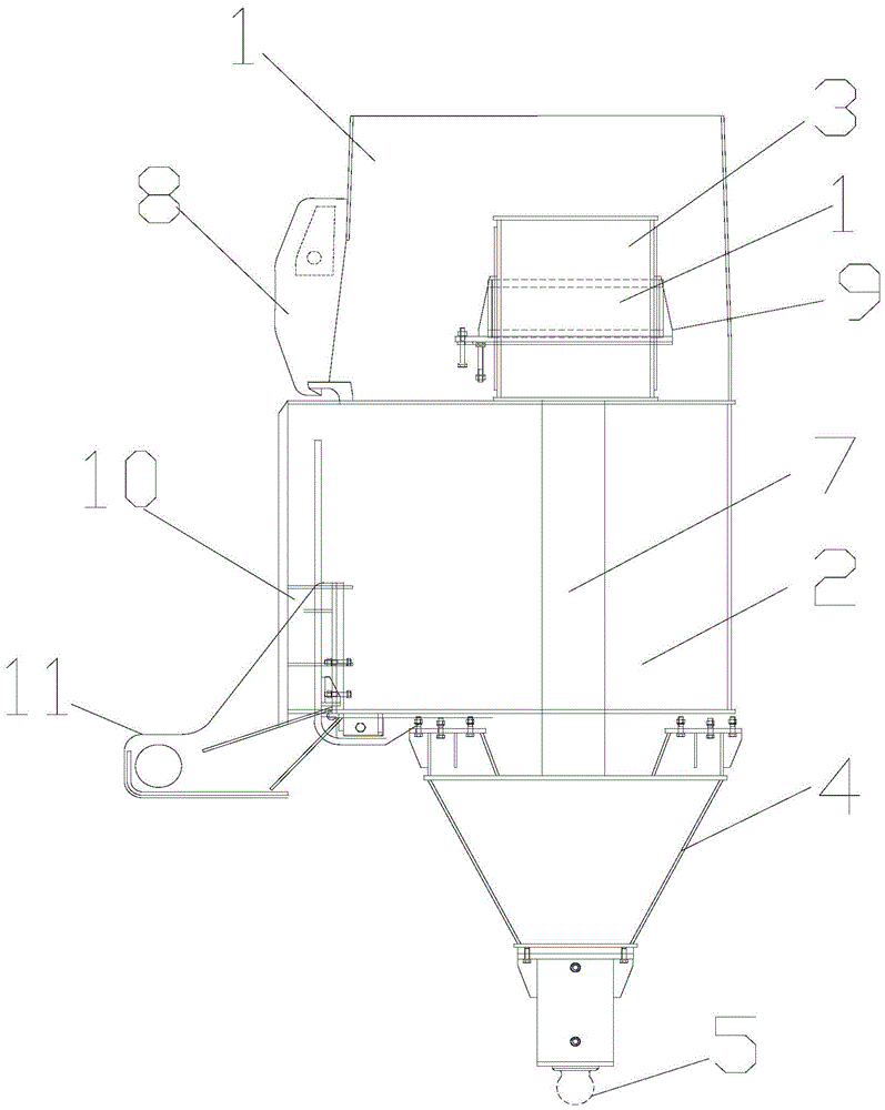
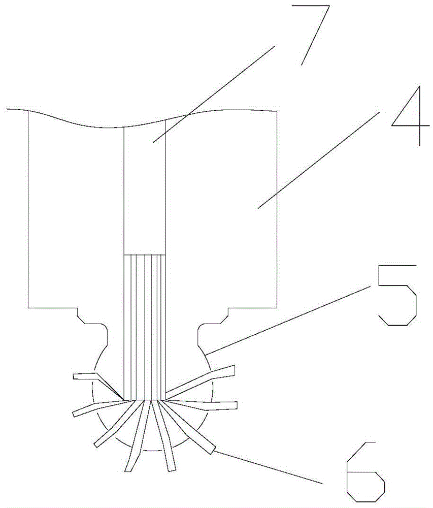
[0019] Such as figure 1 As shown, it is a structural diagram of the bottom of the metal utility pole 1, and the structure of the upper end of the metal utility pole 1 is not shown in the figure. A monitoring auxiliary box 2 is installed below the metal utility pole 1, and an information collection box 3 is installed above the monitoring auxiliary box 2, and a control system, a simple analysis system and a remote transmission system are installed in the information collection box 3, so that The bottom of the monitoring auxiliary box 2 is provided with a sampling head 4 with a conical cross section, the tip of the sampling head 4 is pointed downward, and a sampling ball 5 is provided at the bottom end, the sampling ball 5 is spherical, and the sampling There are detection holes distributed on the outside of the ball 5, and a sampling needle 6 is arranged in the detection hole, and a telescopic connecting arm 7 with a motor is arranged in the monitoring auxiliary box 2, and the t...


PUM


Abstract

The invention aims at overcoming the defects in the prior art, and provides a telegraph pole for environment monitoring. The telegraph pole for environment monitoring is mainly used for monitoring enterprises in an industrial district. In order to achieve the goal, the telegraph pole for environment monitoring comprises a metal telegraph pole, wherein a monitoring auxiliary box is arranged under the metal telegraph pole; a sampling head with the conical cross section is arranged under the monitoring auxiliary box; and a sampling ball is arranged at the end part under the sampling head. The telegraph pole has the advantages that electric equipment is used; the installation and the repair can be performed during the telegraph pole replacement; and an environment protection monitoring device can be protected in the name of electric equipment. Practical pollution sources can be worked out according to the pollution degree condition in different directions through the structure of the sampling ball. A plurality of telegraph poles are generally used in a combined way for covering the whole electricity use region, so that the long-term effective and precise environment protection monitoring can be performed.

Description

technical field [0001] The invention relates to an expansion of electric equipment, in particular to an electric pole for monitoring the environment and an installation method thereof. Background technique [0002] Environmental pollution is a very important issue in today's society. Environmental pollution is mainly divided into two parts, one is the pollution generated by residents' lives, and the other is the pollution generated by the production and manufacturing of enterprises. Due to the different types of environmental pollution, the difficulty of detection is also different. For example, air pollution, ordinary residents may perceive it from the color and smell of the air. The discharge of some heavy metal wastewater or the infiltration of pollutants in the soil cannot be seen intuitively. The amount of pollutant emissions and the intensity of pollution factors change over time. For example, the types and concentrations of pollutants emitted by factories tend to ...

Claims


Application Information

Patent Timeline
Patent Type & Authority Applications(China)
IPC IPC(8): E04H12/00G01N33/24
Inventor 郑腾飞马静君
Owner STATE GRID ZHEJIANG LANXI POWER SUPPLY
Why Eureka
Try Eureka