Valve core assembly of safety valve

A technology of valve core assembly and safety valve

Inactive Publication Date: 2016-05-18
JULONG GROUP WUHU XINGLONG HYDRAULIC
View PDF15 Cites 2 Cited by
  • Summary
  • Abstract
  • Description
  • Claims
  • Application Information

AI Technical Summary

Problems solved by technology

[0004] The overflow channel of the existing safety valve adopts the liquid passage hole arranged around the side wall of the valve core. The diameter of the liquid passage hole is small, resulting in small discharge flow and large flow loss. The seat bears the axial force exerted by the return spring, which leads to poor stress on the valve core and large pressure fluctuations during the working process, which leads to generally unsatisfactory closing pressure of the safety valve, and eventually leads to failure of the hydraulic components connected to the safety valve. Such as excessive loss of oil in the high-pressure cylinder, resulting in waste
The sealing effect between the spool and the valve sleeve is not ideal, and the processing accuracy of the groove on the surface of the spool for installing the seal is not easy to control
In addition, the spring cavity inside the valve housing is in an open state, and the dustproof, waterproof and rustproof effects are poor, which reduces the service life of the safety valve

Method used


Image

  • Valve core assembly of safety valve
  • Valve core assembly of safety valve
  • Valve core assembly of safety valve

Examples


Embodiment Construction

[0037] The specific embodiment of the present invention will be described in further detail by describing the embodiments below with reference to the accompanying drawings, the purpose is to help those skilled in the art to have a more complete, accurate and in-depth understanding of the concept and technical solutions of the present invention, and contribute to its implementation.

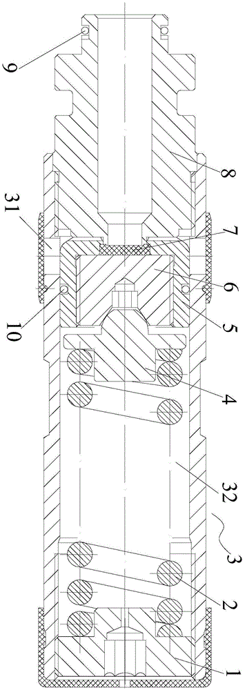
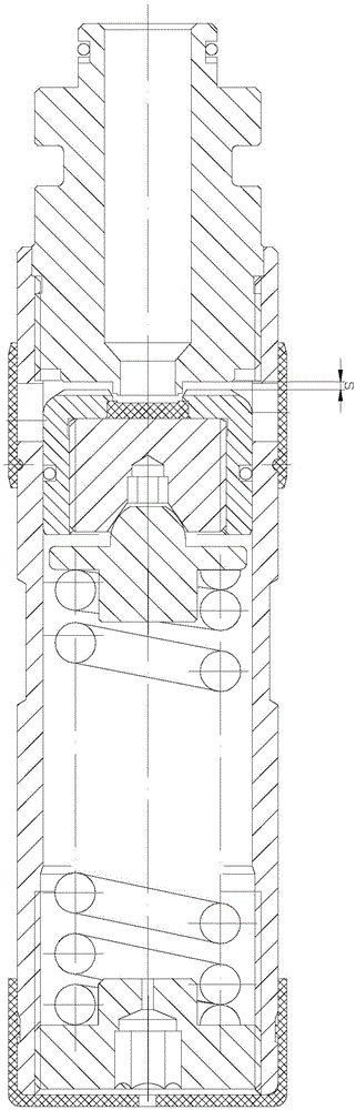
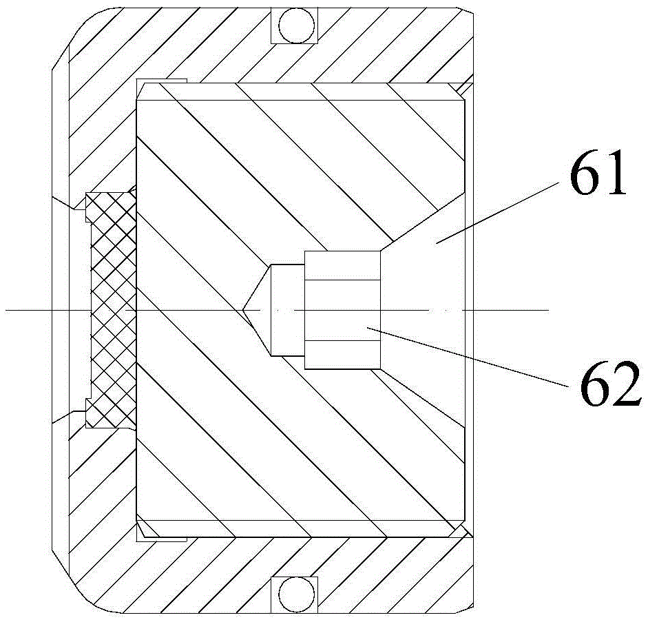
[0038] like Figure 1 to Figure 7 As shown, it is a large-flow overflow safety valve adopting the spool assembly of the present invention. The overflow safety valve includes a valve housing 3 with a liquid discharge hole 31, a liquid inlet joint 8 with a liquid inlet hole, and a reset mechanism. The liquid hole communicates with the liquid discharge hole 31 through the unloading cavity inside the valve housing 3 and the three form an overflow channel of the safety valve. The overflow safety valve also includes the spool assembly of the present invention, the spool assembly of the present inventio...


PUM


Abstract

The invention discloses a valve core assembly of a safety valve. The valve core assembly comprises a screw cap and a valve pad, wherein the valve pad is arranged in the screw cap and is used for being matched with a liquid inlet joint of an overflow safety valve. The valve core assembly is applied to the safety valve, and can be used for controlling the make-and-break state of an oil path from a liquid inlet hole to a liquid discharge hole; when the valve core assembly goes far away from the liquid inlet joint, the high-flow-rate overflow can be realized; the flow rate of the safety valve is greatly improved; the axial displacement of the valve core assembly can be reduced through short-time fast overflow; when the axial displacement of the valve core assembly is reduced, the axial deformation of reset springs can be reduced; and finally, the pressure fluctuation can be reduced.

Description

technical field [0001] The invention belongs to coal mine fully mechanized mining hydraulic support, in particular, the invention relates to a valve core assembly of a safety valve. Background technique [0002] With the large-scale implementation and development of coal mine fully mechanized mining hydraulic supports, fully mechanized mining work has more and more stringent requirements for hydraulic supports, so there are further requirements for the safety valve of the hydraulic cylinder of the protection support, especially for the safety valve There are further requirements for the service life and reliability of the hydraulic support. When the pressure from the top of the hydraulic support causes passive force, whether the safety valve can unload in a short time, fully and stably under the condition of high pressure directly affects the service life of the support. and support security. It will not only damage seals, pipes and hydraulic components, but also cause vibr...

Claims


Application Information

Patent Timeline
Patent Type & Authority Applications(China)
IPC IPC(8): E21D15/51E21D23/26
CPCE21D15/51E21D23/26
Inventor 李福洪朱述群谢瑞李子昂林文彬陶兴陈伟奚光荣高俊强
Owner JULONG GROUP WUHU XINGLONG HYDRAULIC
Why Eureka
Try Eureka