

Centrifugal spiral spinning device
A spinning device and helix technology, applied in the field of centrifugal helical spinning devices, can solve the problems of poor uniformity, poor sealing, complex centrifugal spinning structure, etc., achieve simple equipment structure, reduce viscosity changes, and be beneficial to stability Effect
- Summary
- Abstract
- Description
- Claims
- Application Information
AI Technical Summary
Problems solved by technology
Method used
Image

Examples
Embodiment 1
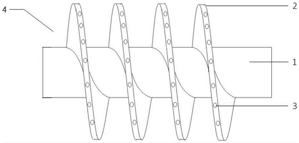
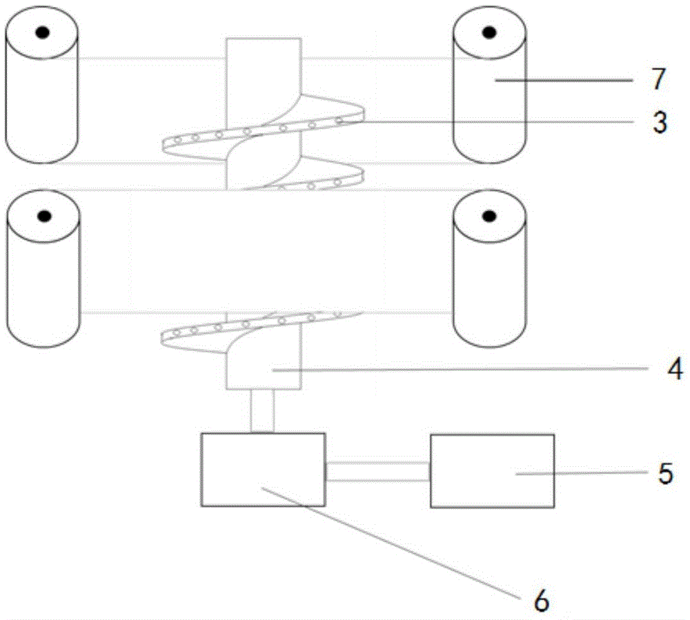
[0032] A centrifugal spiral spinning device, mainly used for processing polymer solution or melt into nanofibers. The centrifugal spiral spinning device comprises the above-mentioned centrifugal spiral spinning head 4, a power system 6, a feed liquid tank 5 and a continuous receiving device 7; Hole 3. The diameter of the hollow screw 1 of the centrifugal spiral spinning head 4 is 30mm, the diameter of the spiral blade 2 is 200mm, the pitch is 100mm, the diameter of the spinneret hole 3 is 0.2mm, and the total length of the centrifugal spiral spinning head 4 is 1200mm.
[0033] The continuous receiving device 7 is two groups of winders parallel to each other. The width of the winders is 1000mm, the distance from the centrifugal spiral spinning head 4 is 480mm, and the speed of the winders is 20m / min.
[0034] Polyvinyl alcohol PVA1799 is used for spinning, PVA1799 powder is added into hot water at 85° C., stirred and dissolved, and a spinning solution having a spinning solutio...
Embodiment 2
[0037] A centrifugal spiral spinning device, mainly used for processing polymer solution or melt into nanofibers. This centrifugal spiral spinning device comprises above-mentioned centrifugal spiral spinning head 4, power system 6, feed liquid tank 5, continuous receiving device 7 and applied electric field device (not shown in the figure); The screw blade 2 of centrifugal spiral spinning head 4 Spinning holes 3 are evenly distributed on the outer end surface perpendicular to the axial direction. The applied electric field device is located between the continuous receiving device 7 and the centrifugal spiral spinning head 4 .
[0038] The diameter of the hollow screw 1 of the centrifugal spiral spinning head 4 is 50 mm, the diameter of the spiral blade 2 is 200 mm, the pitch is 500 mm, the diameter of the spinneret hole 3 is 0.1 mm, and the total length of the centrifugal spiral spinning head 4 is 800 mm.
[0039] The continuous receiving device 7 is two groups of winders par...
Embodiment 3
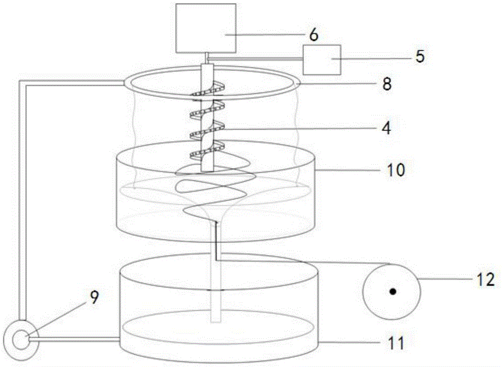
[0042] A centrifugal spiral spinning device, mainly used for processing polymer solution or melt into nanofibers. This centrifugal spiral spinning device comprises above-mentioned centrifugal spiral spinning head 4, power system 6, feed liquid tank 5, continuous receiving device 7 and induction heater (not shown in the figure); Spinning holes 3 are evenly distributed on the outer end surface perpendicular to the axial direction. The continuous receiving device 7 is a vortex solidification receiving device, including four parts: an annular water injection device 8, a vortex pool 10, a liquid collection pool 11, a circulating water pump 9 and a winding device 12. The circulating water pump 9 pumps the liquid from the liquid collection pool 11 into the The annular water injection device 8 forms a water curtain and surrounds the centrifugal spiral spinning head 4, and forms a vortex in the vortex pool 10, and the fibers form fiber bundles under the action of the vortex and are col...
PUM
| Property | Measurement | Unit |
|---|---|---|
| diameter | aaaaa | aaaaa |
| distance | aaaaa | aaaaa |
| distance | aaaaa | aaaaa |
Abstract
Description
Claims
Application Information