Supercharge Your Innovation With Domain-Expert AI Agents!

Card Detect Architecture For Near Field Communications

A near-field communication and detector technology, which is applied in the direction of using transceiver near-field transmission system, wireless communication, near-field transmission system, etc., can solve error indication, high power consumption of NFC reader/writer equipment, etc. question

Inactive Publication Date: 2016-06-29
INTEL CORP
View PDF6 Cites 4 Cited by
  • Summary
  • Abstract
  • Description
  • Claims
  • Application Information

AI Technical Summary

Problems solved by technology

This may result in higher power consumption of the NFC reader / writer device
[0006] Another problem could be the error indicating

Method used


Image

  • Card Detect Architecture For Near Field Communications
  • Card Detect Architecture For Near Field Communications
  • Card Detect Architecture For Near Field Communications

Examples


Embodiment Construction

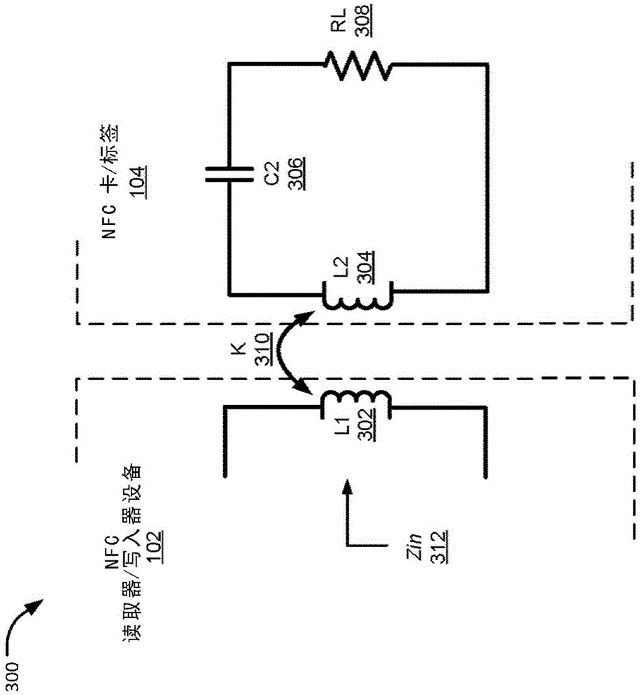
[0015] Described herein are architectures, platforms, and methods for identifying the presence of a Near Field Communication (NFC) card / tag using a uniquely coupled impedance signature by an NFC reader / writer device. The described technique detects the change in impedance when the NFC card / tag is brought into the vicinity of the NFC reader / writer antenna and does not require the NFC card / tag to be powered. False indications can be avoided because other metallic or magnetic objects do not produce unique coupled impedance characteristics.

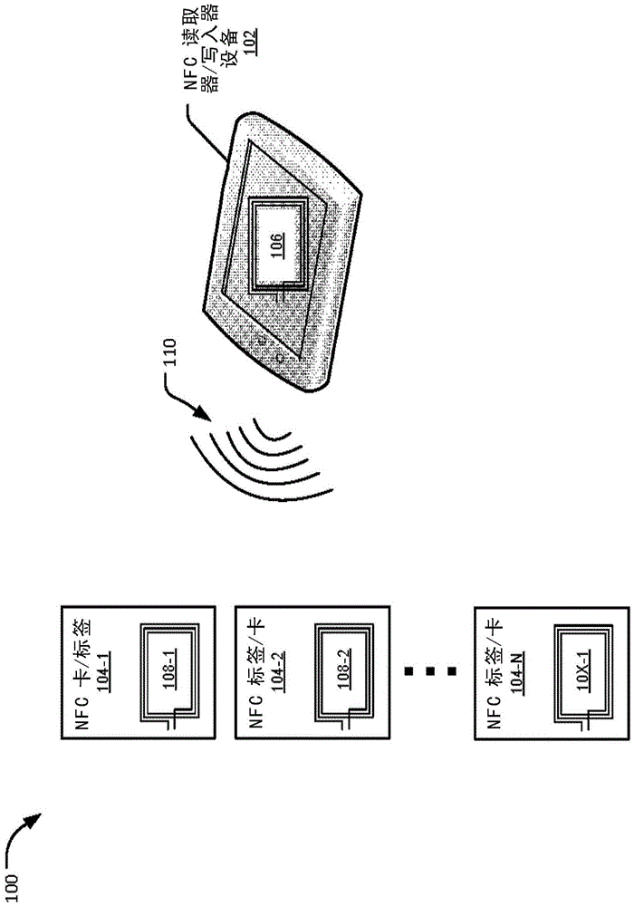
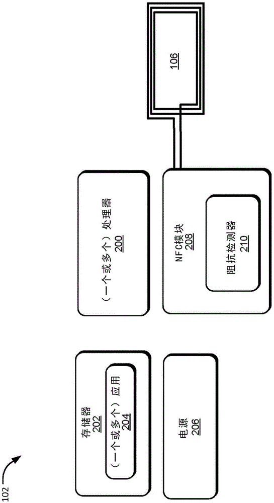
[0016] figure 1 An example scenario 100 illustrating a Near Field Communication (NFC) reader / writer device 102 communicating with one or more NFC cards / tags 104 is shown. The NFC card / tag 104 may be passive or active (ie, unpowered or powered). The NFC reader / writer device 102 includes an antenna 106, which may be part of an NFC module (not shown) or connected to an NFC module (not shown).

[0017] The NFC cards / tags 104 include respective...


PUM


Abstract

The invention relates to a card detect architecture for near field communications. Described herein are architectures, platforms and methods for detecting near field communication (NFC) cards / tags by a NFC enabled device, using a coupled impedance signature unique to the NFC cards / tags and the NFC enabled device.

Description

technical field [0001] The present application generally relates to a card detection architecture for near field communication. Background technique [0002] In systems and devices implementing Near Field Communication (NFC), an NFC reader / writer device can communicate with several NFC enabled cards / tags. Such NFC cards / tags may be passive, meaning they have no power source. In a typical implementation, an NFC reader / writer device attempts to investigate or determine which NFC cards / tags are in its environment. [0003] The antenna of the NFC reader / writer device can transmit radio frequency (RF) fields. When the passive NFC card / tag is brought into the RF field of the NFC reader / writer device, the passive NFC card / tag receives energy and begins to communicate with the NFC reader / writer device. [0004] Before such communication is established between the NFC reader / writer device and the passive NFC card / tag, the NFC reader / writer device detects the presence of the passiv...

Claims


Application Information

Patent Timeline
IPC IPC(8): H04W4/00H04B5/00G06K7/10H04W4/80
CPCH04W4/80G06K7/10118H04B5/70G06K7/10297G06K19/025G06K19/07758G06K19/07783H04B2001/0416G06K19/07781H01Q1/2216H01Q7/005G06K7/00G06K19/07779H03F1/0233H03F3/189H03F3/20H04B1/0458H04B5/77H04B5/24H04B5/26H04B5/266H04B5/48H04B5/72H04B5/79
Inventor 尼兰詹·卡兰笛卡尔蒂莫西·考克斯
Owner INTEL CORP
Features
  • R&D
  • Intellectual Property
  • Life Sciences
  • Materials
  • Tech Scout
  • Unparalleled Data Quality
  • Higher Quality Content
  • 60% Fewer Hallucinations
Learn More