
Piston-cylinder assembly for a disconnecting unit, especially for a master cylinder of a hydraulic clutch actuating device
A separation unit and piston technology, applied in the direction of clutches, fluid-driven clutches, non-mechanical drive clutches, etc., can solve the problems of restricting axial guidance and damaging the function of piston seals, etc.
- Summary
- Abstract
- Description
- Claims
- Application Information
AI Technical Summary
Problems solved by technology
Method used
Image

Examples
Embodiment Construction
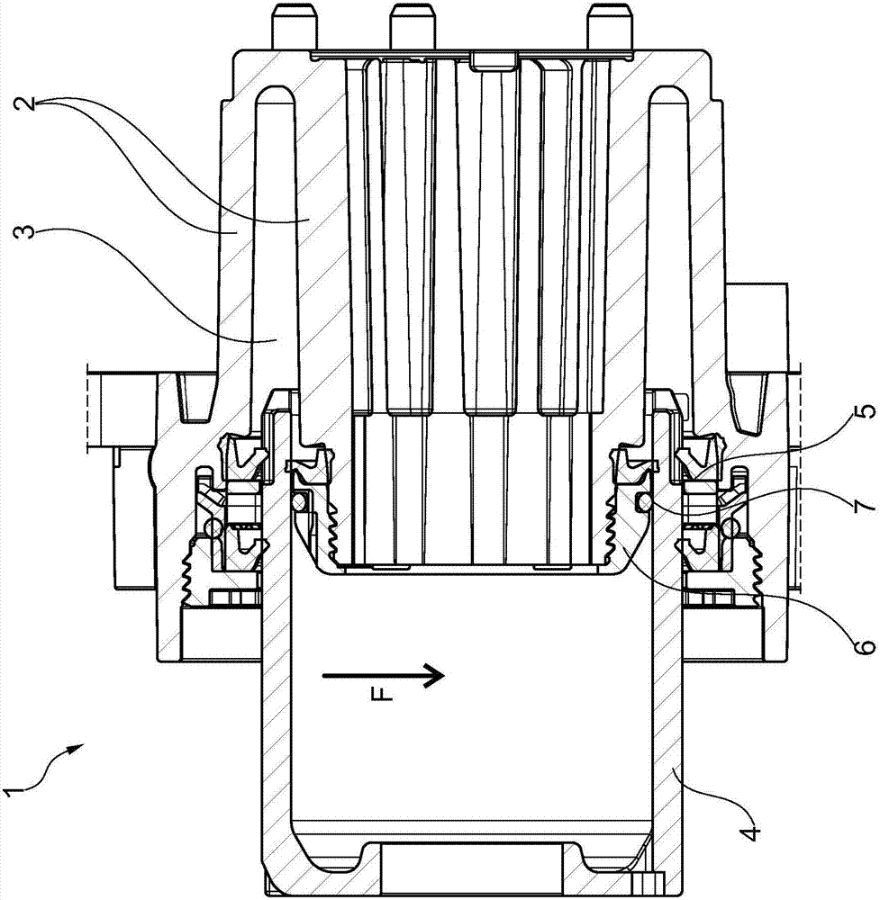
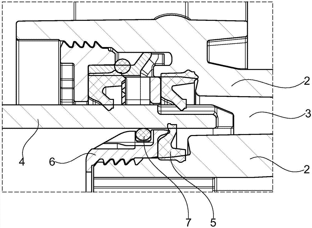
[0018] exist figure 1 shows the master cylinder 1 of a hydraulic clutch actuating device, wherein the cylinder is designed as a housing 2 , wherein the housing 2 expands an annular pressure chamber 3 in which a hydraulic medium is contained. In this case, the piston 4 moves axially, which piston is mounted in the pressure chamber 3 . The piston 4 is actuated by a spindle actuator not shown further and moves hydraulic medium from the pressure chamber into the hydraulic line. Piston 4 is sealed relative to pressure chamber 3 by means of at least one annular seal 5 . as in figure 1 As shown in , there is also the possibility of using double seal rings.
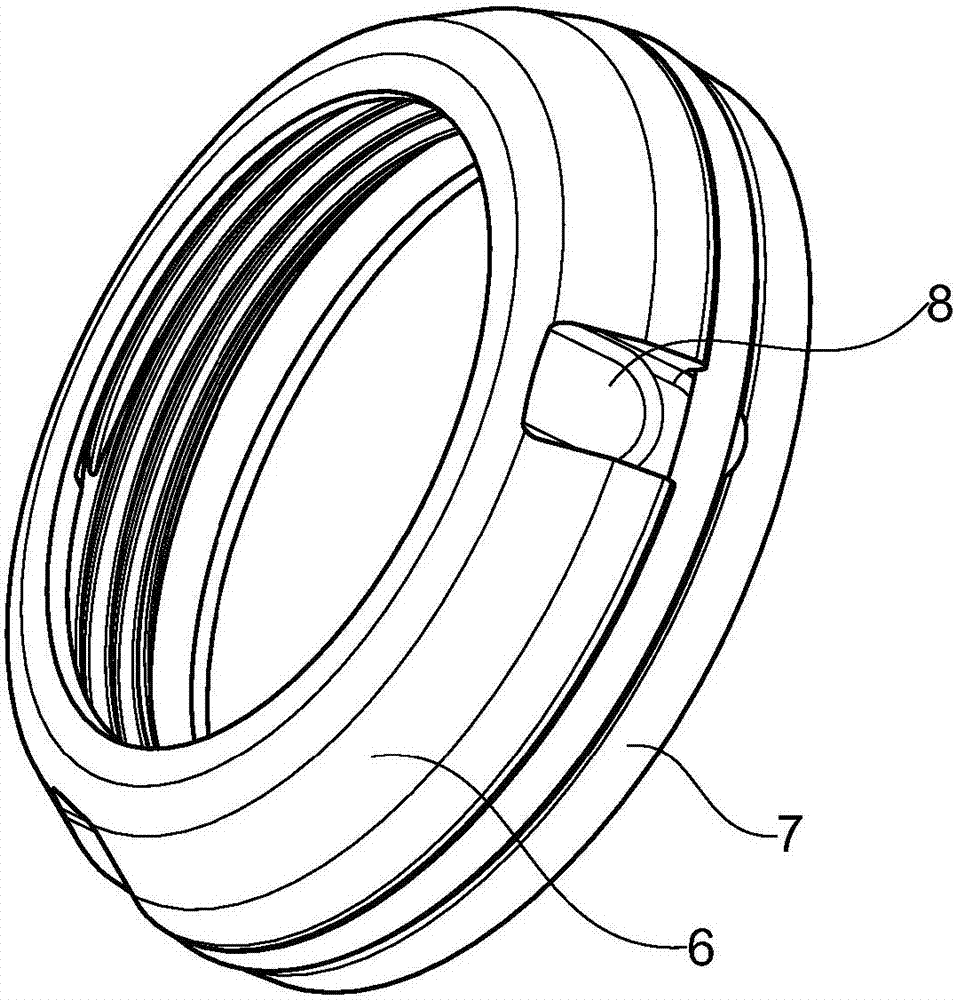
[0019] The seal 5 is also designed annularly, whereby two sealing points result. Arranged on the housing 2 is an annular intermediate support 6 on which a guide element 7 , preferably an O-ring made of a relatively soft material, preferably an elastomer, is supported. In this case, the guide element 7 is arranged parallel to...
PUM
 Abstract
Description
Claims
Application Information