
A sliding vane type residual pressure recovery device
A recovery equipment and sliding vane technology, applied in mechanical equipment, rotary piston pumps, rotary piston machinery, etc., can solve the problems of complex control system, complex structure, and small processing capacity of a single machine
- Summary
- Abstract
- Description
- Claims
- Application Information
AI Technical Summary
Problems solved by technology
Method used
Image

Examples
Embodiment Construction
[0047] The present invention will be further described in detail below in conjunction with specific embodiments, which are explanations of the present invention rather than limitations.
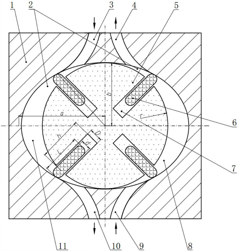
[0048] see figure 1 , a sliding vane type residual pressure recovery device, comprising a cylinder 1, a rotor 5 is arranged in the inner chamber 2 of the cylinder 1, and the rotor 5 divides the inner chamber 2 into a left chamber 11 and a right chamber 8, and the left chamber The upper and lower ends of the chamber 11 communicate with the high-pressure inlet hole 3 and the low-pressure outlet hole 10 respectively, and the upper and lower ends of the right chamber 8 communicate with the high-pressure outlet hole 4 and the low-pressure inlet hole 9 respectively. The rotor 5 is provided with a plurality of slots 7, and the sliding vanes 6 are arranged in the slots 7, and the rotor profile of the rotor 5 is circular.
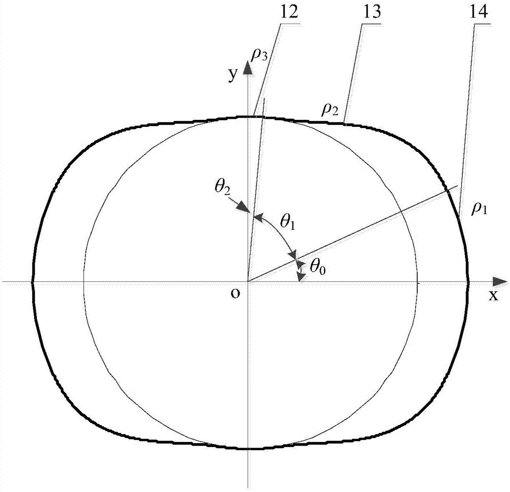
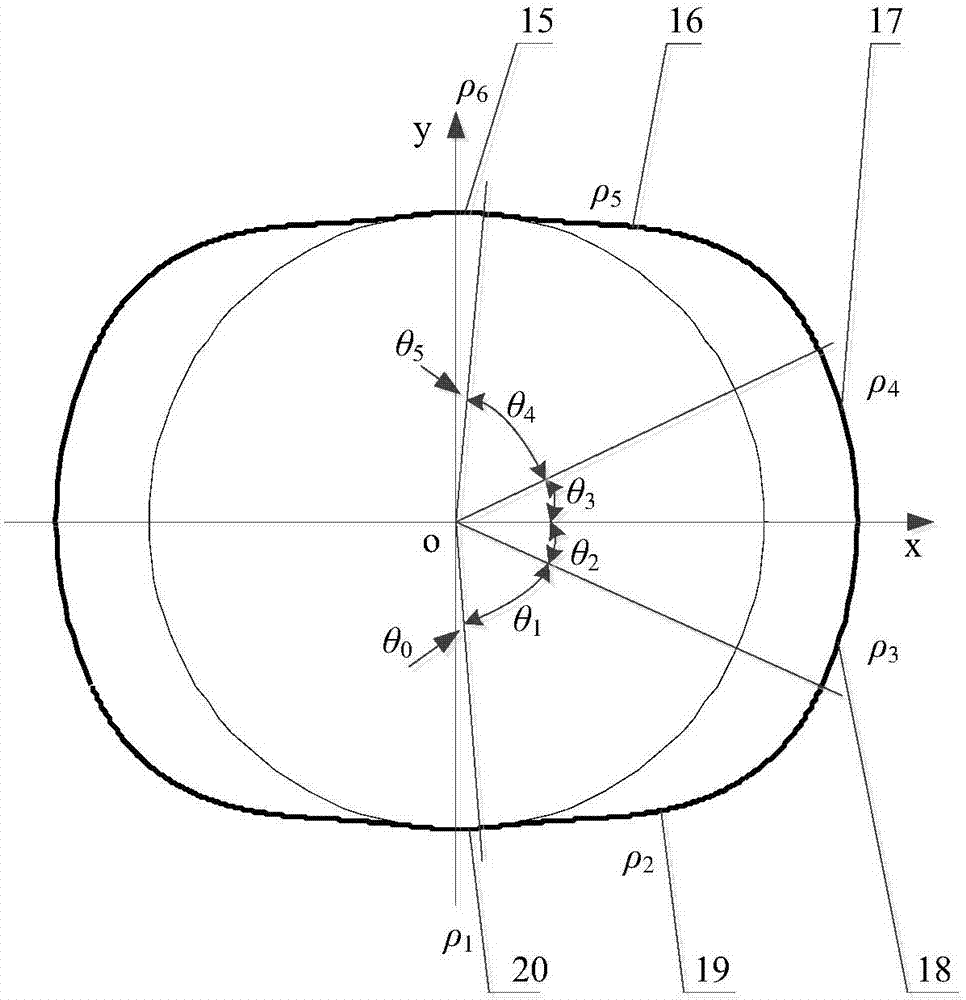
[0049] The main curve sections of the cylinder body molding lines in the left...
PUM
 Abstract
Description
Claims
Application Information