Urban trunk road vehicle trajectory reconstruction method based on fixed-point detector and signal timing data fusion

A vehicle trajectory and data fusion technology, applied in the field of traffic information, can solve the problem of low data quality of floating vehicles

Active Publication Date: 2016-07-20
连云港杰瑞电子有限公司
View PDF4 Cites 40 Cited by
  • Summary
  • Abstract
  • Description
  • Claims
  • Application Information

AI Technical Summary

Problems solved by technology

[0009] The technical problem to be solved by the present invention aims at the low quality of floating car data in our country, integrates the existing fixed-point detector data and traffic signal data, and determines some parameters in combination with video data, and proposes A vehicle trajectory reconstruction method for urban arterial roads based on th

Method used


Image

  • Urban trunk road vehicle trajectory reconstruction method based on fixed-point detector and signal timing data fusion
  • Urban trunk road vehicle trajectory reconstruction method based on fixed-point detector and signal timing data fusion
  • Urban trunk road vehicle trajectory reconstruction method based on fixed-point detector and signal timing data fusion

Examples


Embodiment 1

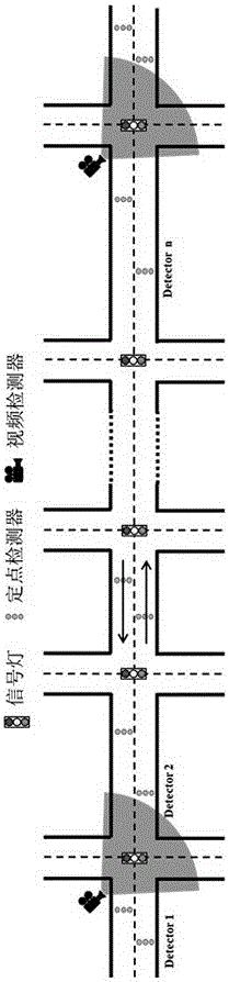
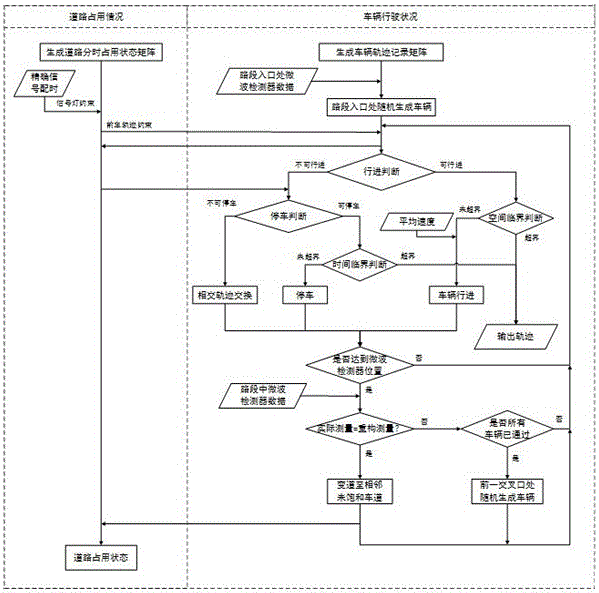
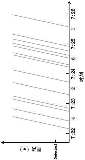
[0073] Embodiment 1, with reference to Figure 2-Figure 8 , a vehicle trajectory reconstruction method on urban arterial roads based on fusion of fixed-point detectors and signal timing data, including the following steps:

[0074] Step 1: Establish the basic matrix

[0075] Establish a three-dimensional road time-sharing occupancy matrix Point[n,distance,t] (n represents the lane, distance represents the distance from the point to the starting point of the research section, and t represents the research time). The function of this matrix is ​​to reflect the real-time road conditions at the current moment (for example, at 30 seconds, there is a 5-meter-long vehicle at 20 meters from the first lane, then [1,15,30] to [1,20,30] are set as occupied), And it is used as a constraint to form a constraint on the generation and operation of the next second vehicle.

[0076] Establish a two-dimensional vehicle operation matrix Car[vehicle,t] (vehicle represents the number of the vehi...

Embodiment 2

[0115] Example 2, see Figure 9 to Figure 13 . It should be noted that the diagrams provided in this embodiment are only schematically illustrating the basic idea of ​​the present invention, so only the components related to the present invention are shown in the drawings rather than the number, shape and Dimensional drawing, the type, quantity and proportion of each component can be changed arbitrarily during actual implementation, and the component layout type may also be more complicated.

[0116] A vehicle trajectory reconstruction method on urban arterial roads based on fusion of fixed-point detectors and signal timing data, which can reconstruct high-precision vehicle trajectories in the case of multiple lanes and traffic interference from vehicles entering and exiting.

[0117] The establishment of this method includes the following steps:

[0118] 1) Data collection and processing

[0119] The section from Shandong Road, Hong Kong Middle Road, Shinan District, Qingd...


PUM


Abstract

The invention provides an urban trunk road vehicle trajectory reconstruction method based on fixed-point detector and signal timing data fusion. The method comprises the following steps: 1) establishing a basis matrix: determining a road occupation condition matrix Point[n, distance, t] at the t moment according to a vehicle running matrix Car [vehicle, t] at the t time, and then, calculating vehicle most probable running status at the t+t0 moment according to the road occupation condition matrix Point[n, distance, t], and thus a Car [vehicle, t+t0<->] constant iterative process is generated; 2) carrying out vehicle generating; 3) carrying out vehicle behavior decision; and 4) judging whether trajectory reconstruction is finished. The method has the advantages of fusing fixed-point detector and signal timing data, not depending on high-quality floating car data and demanding less on traffic data acquisition environment. The method is suitable for multilane and coming/going vehicle traffic interference cases, is wide in applicability, is complete and comprehensive in reconstructed trajectory, and can realize the functions of environment assessment, signal control coordination, travel time estimation and jam state early warning and the like.

Description

technical field [0001] The invention belongs to the field of traffic information, and in particular relates to a method for reconstructing urban main road vehicle tracks based on fusion of fixed-point detectors and signal timing data. Background technique [0002] In the field of traffic engineering, there are two levels of cognition and understanding for vehicle trajectory reconstruction: the first level is the driving path of the vehicle, which refers to the starting and ending points of the vehicle and the road sections and nodes connecting the starting and ending points. Estimation of the OD (OriginDestination) matrix of the road network; the second level is the running trajectory of the vehicle, which refers to the complete physical trajectory of the vehicle during the driving process, which can reflect the change law of the vehicle speed with time and space. The present invention is aimed at the reconstruction of the second-level vehicle running trajectory. The vehicle...

Claims


Application Information

Patent Timeline
IPC IPC(8): G08G1/01
CPCG08G1/0116G08G1/0125
Inventor 项俊平唐克双刘伟张锋鑫刘建华
Owner 连云港杰瑞电子有限公司
Why Eureka
Try Eureka