
Electric winding device with replaceable platen

A pressure plate, electric technology, applied in projection devices, door/window protection devices, optics, etc., to avoid direct scrapping

Active Publication Date: 2018-06-19
孙毅
View PDF10 Cites 0 Cited by
  • Summary
  • Abstract
  • Description
  • Claims
  • Application Information

AI Technical Summary

Problems solved by technology

This phenomenon may not appear for a long time in screen products with slow speed and few times of use, but it may be unavoidable in classroom roller blind products with fast running speed (such as about 3 times the screen speed) and frequent ups and downs for many years

Method used


Image

  • Electric winding device with replaceable platen
  • Electric winding device with replaceable platen
  • Electric winding device with replaceable platen

Examples


Embodiment Construction

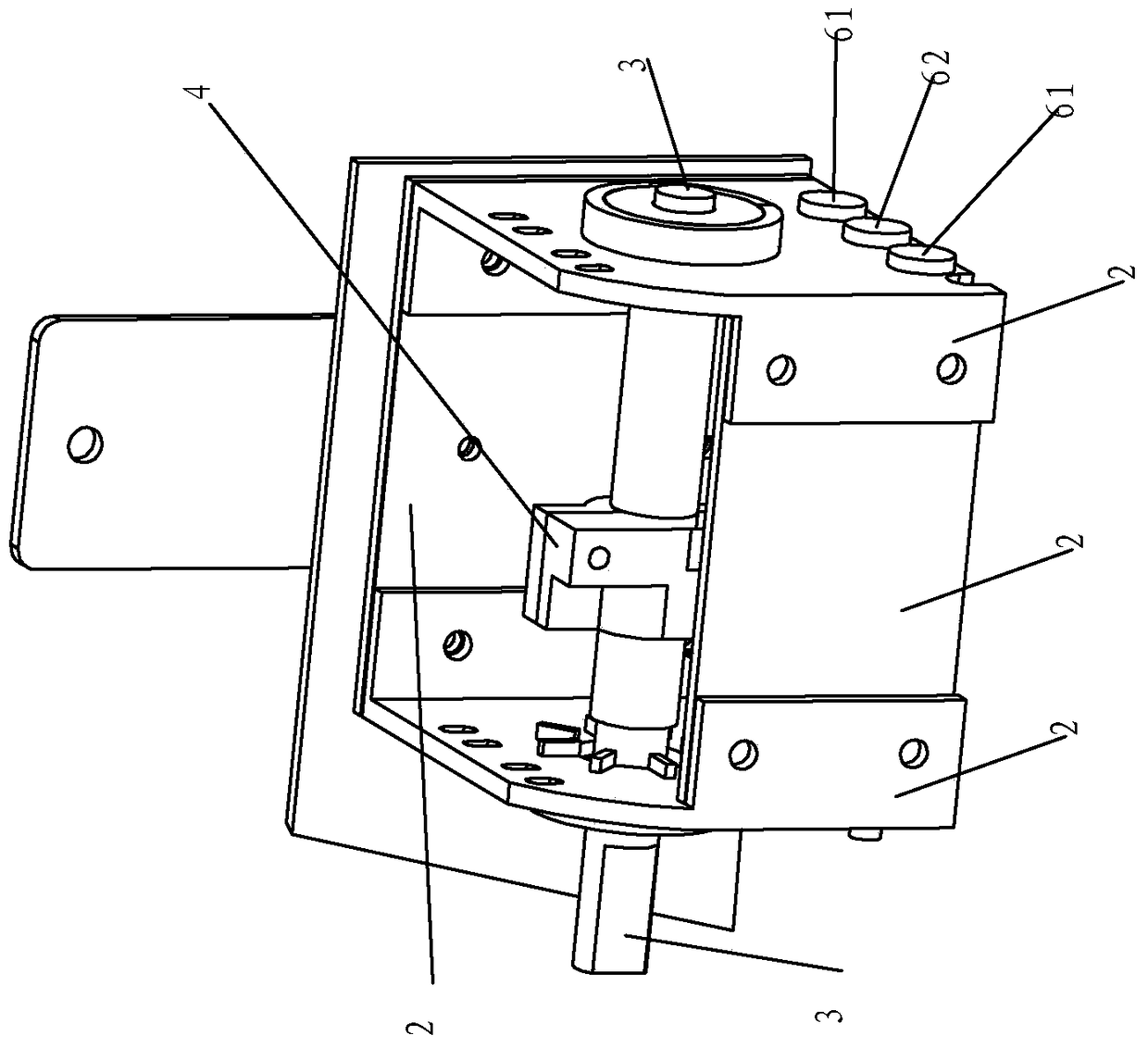
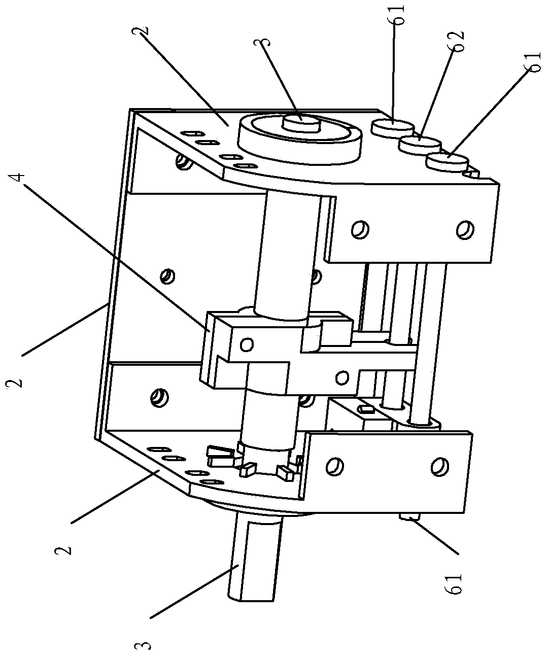
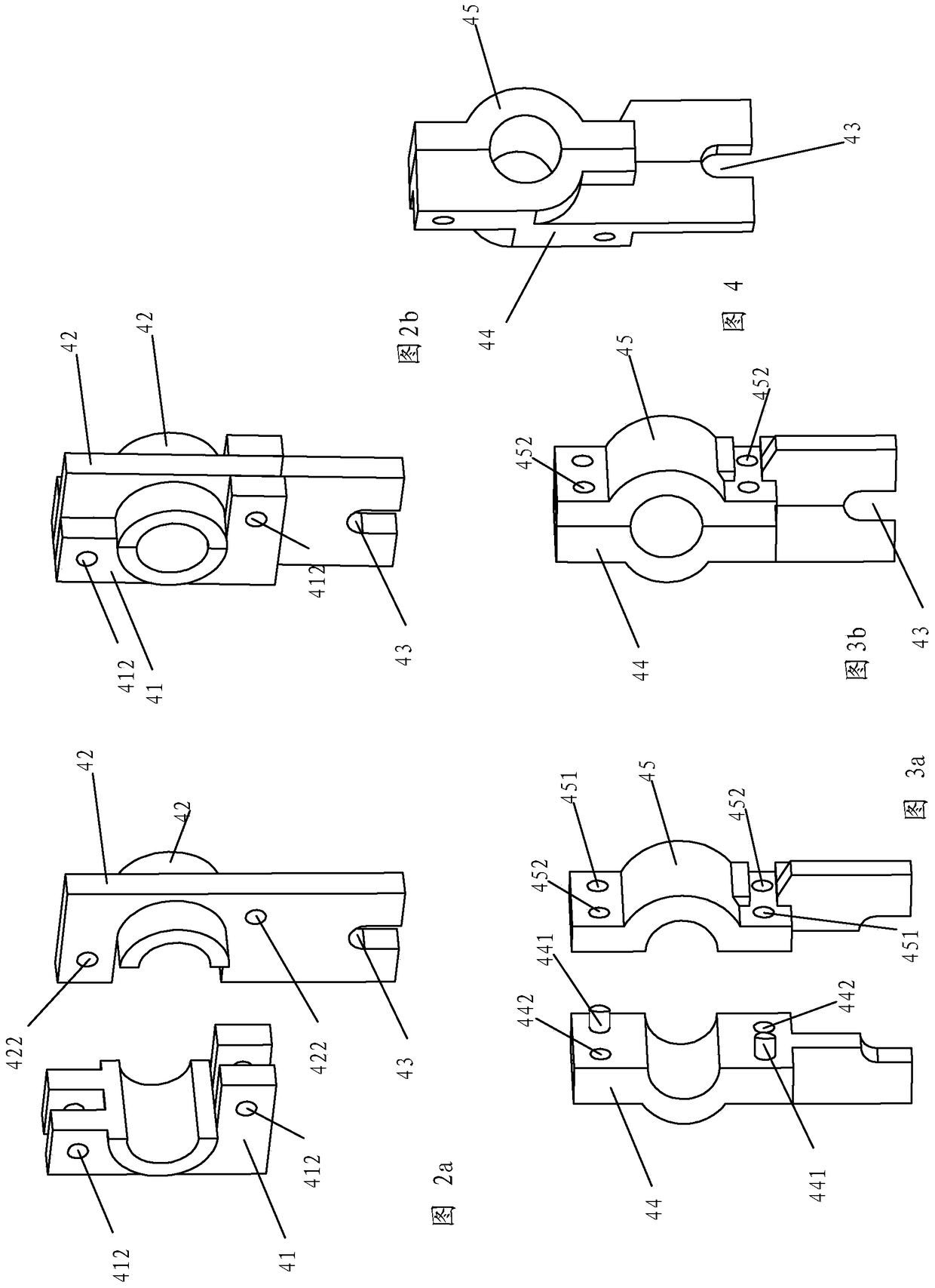
[0013] Example. see Figure 1a -b: The auxiliary end of the electric screen product includes the auxiliary end frame (2), the slave shaft screw (3), the pressure plate (4), the micro switch (51), the switch seat (52), the debugging bottom rod (61), the center Bottom rod (62) etc. The forward rotation and reverse rotation of the output shaft of the electric screen motor drive the forward rotation and reverse rotation of the roll tube that loads the screen cloth, and then determine the forward rotation and reverse rotation of the slave shaft screw (3) mounted in the auxiliary end frame (2) . The upper part of the pressure plate (4) is a nut matching the slave shaft screw (3), and the ∩-shaped opening (43) of the lower part of the pressure plate (4) is fastened to the midsole rod (62). When the middle bottom rod (62) prevents the ∩-shaped opening (43) from rotating with the upper nut, the forward rotation and reverse rotation of the slave shaft screw (3) will cause the nut of t...


PUM


Abstract

Electric roll-hanging device with replaceable pressure plate, related to electric screen and electric roller blind products, it includes shell panel detachable relative to shell back plate, synchronous reversible micro-motor, roll tube, curtain or curtain, including slave shaft screw , micro switch, debugging bottom bar, auxiliary end of mid-sole bar, and especially includes a detachable and replaceable combined pressure plate. This design supports ordinary users to directly replace the pressure plate on the slave shaft screw, which greatly reduces product maintenance costs.

Description

technical field [0001] The present invention relates to an electric wind-up device with a replaceable pressure plate for a screen or curtain to be rolled up. Background technique [0002] Electric screen and electric roller blind products include housing, synchronous reversible micro-motor, roller tube, curtain / curtain, and auxiliary end frame including slave shaft screw, pressure plate, micro switch, switch seat, and adjustment bottom rod. The double-layer electric roller blinds that operate independently of each other include two components of the electric single roller blind except the casing. [0003] In the use of various electric coil hanging products, the closed round hole at the lower end of the pressure plate is pierced by the limit bottom rod, and the nut hole at the top of the pressure plate is pierced by the screw section of the slave shaft. As the slave shaft rotates forward and reverse according to the motor, the pressure plate The nut moves linearly from left...

Claims


Application Information

Patent Timeline
Patent Type & Authority Patents(China)
IPC IPC(8): G03B21/58E06B9/68
Inventor 孙毅
Owner 孙毅
Learn More