
Permanent magnet electric welding and generator dual-use equipment
A technology of electric welding generator and permanent magnet, applied in synchronous motors, magnetic circuits, synchronous machines with static armatures and rotating magnets, etc. The effect of failure operation ability and stable work
- Summary
- Abstract
- Description
- Claims
- Application Information
AI Technical Summary
Problems solved by technology
Method used
Image

Examples
Embodiment Construction
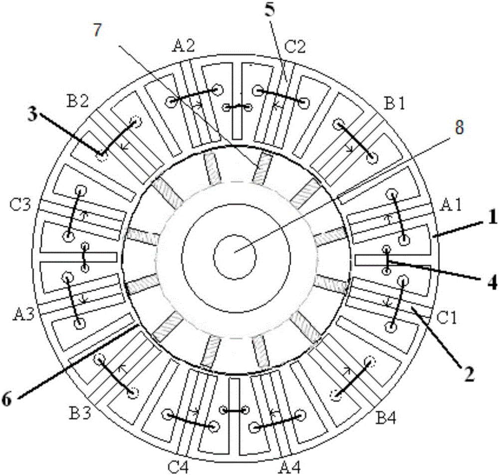
[0010] See figure 1 The permanent magnet welding generator of the present invention includes a stator 1 and a rotor 6. The rotor 6 is located inside the stator 1. Four three-phase windings 3 are arranged on the stator 1. The rotor 6 is embedded with permanent magnet strips 7 and E-shaped conductive magnets. Core 2, winding 3, sensor 4, permanent magnet 5, rotor shaft 8.
[0011] The stator core consists of 12 E-shaped conductor core unit openings evenly distributed inward on the ring. A conductor magnet is embedded between every two E-shaped conductor cores, that is, two adjacent E-shaped conductor cores. The permanent magnet 5 sandwiched between the conductor core constitutes the iron core teeth; the winding is wound in the slot of the "E"-shaped stator punched piece with silicon steel sheet, and the winding coil: the entire circumference of the E-shaped conductor core is evenly placed in the stator slot. Group independent three-phase welding windings, that is, four independent...
PUM
 Abstract
Description
Claims
Application Information