
Multi-rotor power testing device and method

A test device, multi-rotor technology, applied in ground devices, transportation and packaging, aircraft parts, etc., can solve the problems of complex structure, large volume and high cost, and achieve the effect of reducing risks

Active Publication Date: 2016-09-21
NANJING NORTH OPTICAL ELECTRONICS
View PDF5 Cites 17 Cited by
  • Summary
  • Abstract
  • Description
  • Claims
  • Application Information

AI Technical Summary

Problems solved by technology

The test platform has high cost, complex structure, and large volume, and can only test a pair of propellers at the same time, which is not suitable for small aircraft such as multi-rotors.

Method used


Image

  • Multi-rotor power testing device and method
  • Multi-rotor power testing device and method

Examples


Embodiment Construction

[0031] In order to better understand the technical content of the present invention, specific embodiments are given together with the attached drawings for description as follows.

[0032] Aspects of the invention are described in this disclosure with reference to the accompanying drawings, which show a number of illustrated embodiments. Embodiments of the present disclosure are not necessarily intended to include all aspects of the invention. It should be appreciated that the various concepts and embodiments described above, as well as those described in more detail below, can be implemented in any of numerous ways, since the concepts and embodiments disclosed herein are not limited to any implementation. In addition, some aspects of the present disclosure may be used alone or in any suitable combination with other aspects of the present disclosure.

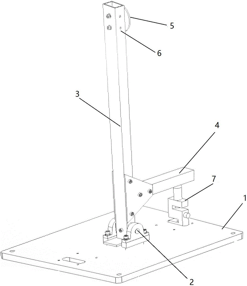
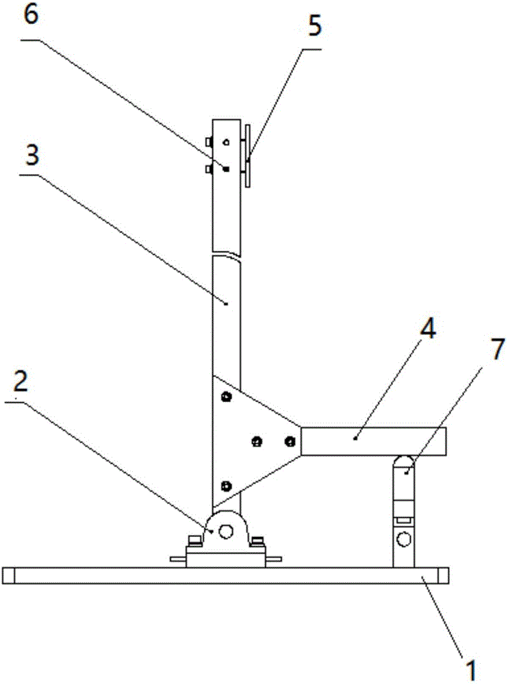
[0033] combine figure 1 , figure 2 As shown, a multi-rotor power test device includes a test base 1, a bearing 2, a verti...


PUM


Abstract

The invention provides a multi-rotor power testing device, comprising a testing base, a bearing, a vertical arm of force, a horizontal arm of force, and a pressure sensor, wherein the bearing is mounted on the testing base and used for changing directions of tensile and torque generated by a propeller under test during a test, the vertical arm of force is connected directly with the bearing, the horizontal arm of force is vertically mounted below the vertical arm of force, the vertical arm of force is rigidly connected with the horizontal arm of force, a push test mounting face and a torque test mounting face for the propeller are formed above the vertical arm of force, the push test mounting face is perpendicular to the torque test mounting face, and the pressure sensor is mounted below the horizontal arm of force, between the horizontal arm of force and the testing base. A testing system of the invention enables power performance and electrical performance of a multi-rotor unmanned aerial vehicle to be tested effectively and safely and may also meet testing requirements of rotor unmanned aerial vehicles with different arm numbers and driving units of different types.

Description

technical field [0001] The invention relates to the technical field of multi-rotor aircraft, in particular to a multi-rotor dynamic testing device and method. Background technique [0002] The power system and the power system are the two most important parts of the multi-rotor UAV. In the power system, the matching between the propeller and the motor, and the efficiency of the propeller are directly related to the performance and life of the drone. The power system provides reliable and continuous energy for the power system. Therefore, it is necessary to develop an effective test platform to accurately obtain the power requirements and energy requirements of the multi-rotor system, which is intuitively important to ensure the safety and reliability of the entire multi-rotor UAV. [0003] The multi-rotor UAV power and power test platform is used to test the performance of the power system on the one hand, and on the other hand, during the ground test, try to test the powe...

Claims


Application Information

Patent Timeline
Patent Type & Authority Applications(China)
IPC IPC(8): B64F5/00
Inventor 刘萍张功学杨柳吴坚耿其亚崔乐何晓莹
Owner NANJING NORTH OPTICAL ELECTRONICS
Learn More