Automobile sliding door system

A technology for sliding doors and automobiles, which is applied in the direction of windows/doors, door/window accessories, special equipment for doors/windows, etc. It can solve the disadvantages of vehicle NVH performance improvement, affect the side shape of the vehicle, and large window frame size, etc. question

Active Publication Date: 2016-09-21
GUANGZHOU AUTOMOBILE GROUP CO LTD
View PDF7 Cites 3 Cited by
  • Summary
  • Abstract
  • Description
  • Claims
  • Application Information

AI Technical Summary

Problems solved by technology

[0004] 1. The size of the window frame is large due to the arrangement of the upper guide rail on the upper part of the door opening, which does not match the window frame of the front door. The joint between the sliding door and the side wall needs to go around the roof position, which destroys the integrity of the side wall and affects the side shape of the vehicle. ;
[0005] 2. The structure of the upper guide rail adopts a built-in structure. There will be a large space on the interior ceiling to hide the guide rail, and it will also affect the arrangement of the ceiling safety air curtain;
[0006] 3. Due to the relationship between the upper guide rail, the sliding door cannot be equipped with a complete set of secondary seals, which is not conducive to the improvement of the NVH performance of the vehicle

Method used


Image

  • Automobile sliding door system
  • Automobile sliding door system
  • Automobile sliding door system

Examples


Embodiment Construction

[0030] The following will clearly and completely describe the technical solutions in the embodiments of the present invention with reference to the accompanying drawings in the embodiments of the present invention. Obviously, the described embodiments are only some, not all, embodiments of the present invention. Based on the embodiments of the present invention, all other embodiments obtained by persons of ordinary skill in the art without creative efforts fall within the protection scope of the present invention.

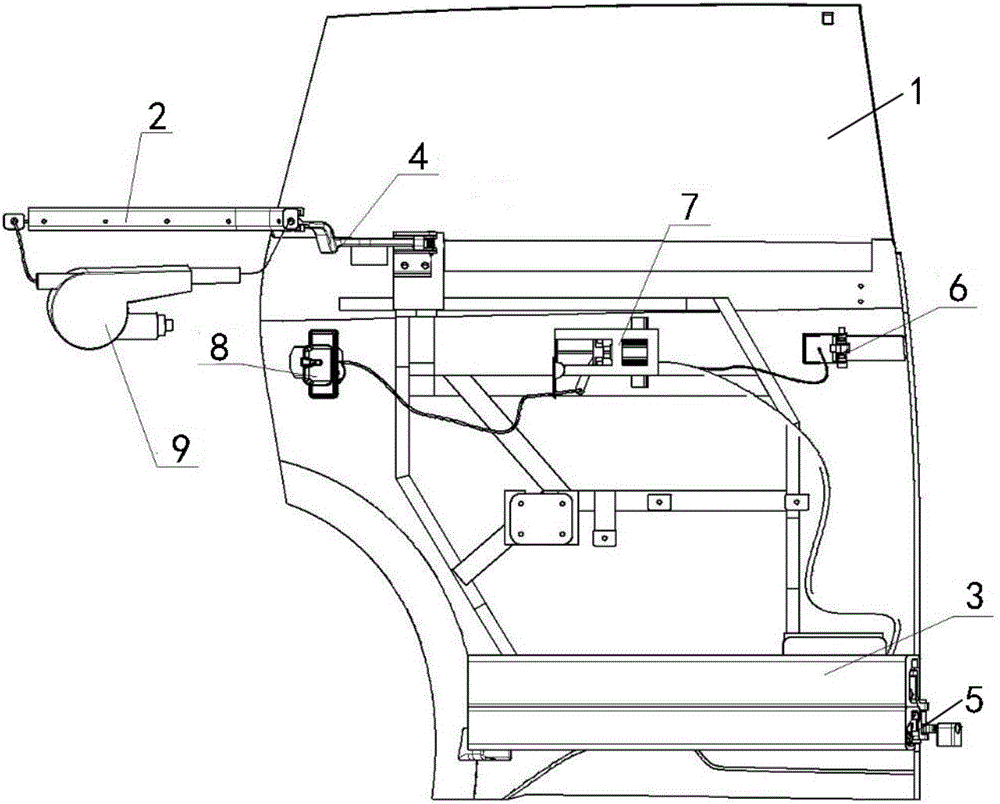
[0031] see figure 1 , which is a schematic structural diagram of an automobile sliding door system provided by an embodiment of the present invention.

[0032]The automobile sliding door system comprises a sliding door body 1, a middle guide rail 2 and a lower guide rail 3; The lower part of the sliding door body 1 is provided with a middle hinge 4 cooperating with the middle guide rail 2, and the lower part of the sliding door body 1 is provided with a lower hing...


PUM


Abstract

The invention discloses an automobile sliding door system. The automobile sliding door system comprises a sliding door body, a middle guide rail and a lower guide rail, wherein a middle hinge matched with the middle guide rail is arranged in the middle of the sliding door body and a lower hinge matched with the lower guide rail is arranged at the lower part of the sliding door body; the lower guide rail comprises a lower guide rail upper transverse wall, a lower guide rail lower transverse wall and a lower guide rail vertical wall for connecting the lower guide rail upper transverse wall and the lower guide rail lower transverse wall; the lower guide rail further comprises a first vertical overturning edge which is connected with the lower guide rail upper transverse wall and a first guide groove which is formed by the first vertical overturning edge, the lower guide rail upper transverse wall and the lower guide rail vertical wall in a surrounding manner and has a downward opening; the lower hinge comprises a lower hinging part and a lower bearing part; the lower bearing part comprises a first bearing and a second bearing; the first bearing rolls along the lower guide rail vertical wall or the first vertical overturning edge by taking the vertical direction as the axial direction; the second bearing rolls along the upper surface of the lower guide rail lower transverse wall by taking the direction vertical to the lower guide rail vertical wall as the axial direction. According to the automobile sliding door system, an upper guide rail is not used under the condition of not influencing an original sliding function of the sliding door system, the integrity of a side wall structure is guaranteed and a good opening/closing performance is obtained.

Description

technical field [0001] The invention relates to the technical field of automobile design, in particular to an automobile and its electric sliding door system. Background technique [0002] At present, most of the sliding door technical solutions adopted by domestic traditional medium and large vehicles are in the form of three guide rails. The upper guide rail and upper hinge provide ±Y-direction (perpendicular to the direction of the side door) degree of freedom restriction, the middle guide rail provides ±Y-direction degree of freedom restriction and auxiliary load-bearing, and the lower guide rail is responsible for the main load-bearing (restriction + Z-direction degree of freedom). The Y direction of the upper guide rail and the middle guide rail is always in the opposite direction, and the generated torque around the X direction (moving direction of the side door) is used to offset the torsion during the opening process of the sliding door. [0003] The inventor of th...

Claims


Application Information

Patent Timeline
Patent Type & Authority Applications(China)
IPC IPC(8): E06B3/46E06B7/28E05D15/06E05D13/00
CPCE05D13/00E05D15/0621E05D15/0686E05Y2201/628E05Y2900/531E06B3/4636E06B7/28
Inventor 卢卓宇冯小奕施宇峰
Owner GUANGZHOU AUTOMOBILE GROUP CO LTD
Why Eureka
Try Eureka