
Air conditioner and control method thereof

An air conditioner and control valve technology, which is applied in heating and ventilation control systems, refrigerators, heating methods, etc., can solve the problems of large heat exchange area of ​​indoor heat exchangers, accumulation of refrigerant in indoor heat exchangers, etc., to avoid absorption Increase the specific volume of gas, avoid the reduction of exhaust pressure and return air pressure, and solve the effect of excessive heat exchange area

Active Publication Date: 2016-09-21
GD MIDEA HEATING & VENTILATING EQUIP CO LTD +1
View PDF5 Cites 21 Cited by
  • Summary
  • Abstract
  • Description
  • Claims
  • Application Information

AI Technical Summary

Problems solved by technology

For this reason, the present invention proposes an air conditioner, which can effectively solve the problem that the heat exchange area of ​​the indoor heat exchanger is too large when the air conditioner is in heating operation, the outdoor ambient temperature is lowered or the air conditioner is in a part-load operation state. Solve the problem of refrigerant accumulation in the shielded part of the indoor heat exchanger in the related art

Method used


Image

  • Air conditioner and control method thereof
  • Air conditioner and control method thereof
  • Air conditioner and control method thereof

Examples


Embodiment 1

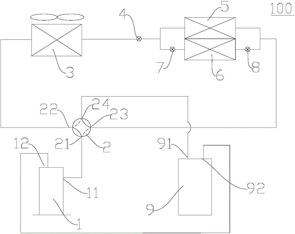
[0054] like figure 1 As shown, the air conditioner 100 in this embodiment includes a compressor 1, a reversing assembly 2, an outdoor heat exchanger 3, a throttling element 4, and a first indoor heat exchanger connected in parallel in the same indoor unit. 5 and the second indoor heat exchanger 6, the first control valve 7 and the second control valve 8. Wherein, both the first control valve 7 and the second control valve 8 are electromagnetic valves. The throttling element 4 is an electronic expansion valve.

[0055]Specifically, the compressor 1 has an exhaust port 11 and an air return port 12. The reversing assembly 2 includes a first valve port 21 to a fourth valve port 24. When the air conditioner 100 is cooling, the first valve port 21 and the second valve port 22 The third valve port 23 communicates with the fourth valve port 24 , and the first valve port 21 communicates with the third valve port 23 and the second valve port 22 communicates with the fourth valve port ...

Embodiment 2

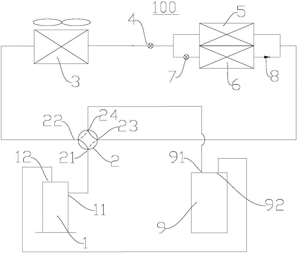
[0066] like figure 2 As shown, the difference between this embodiment and Embodiment 1 is that the second control valve 8 is a one-way valve that conducts in one direction in the direction from the second indoor heat exchanger 6 to the third valve port 23 . In this embodiment, the working principle of the air conditioner 100 in cooling mode is the same as that in Embodiment 1 above.

[0067] It can be understood that when the air conditioner 100 is in the heating mode, since the second control valve 8 is a one-way valve, no refrigerant flows in the direction from the third valve port 23 to the second indoor heat exchanger 6 all the time. The second indoor heat exchanger 6, that is, the second indoor heat exchanger 6 is always in a shielded state. Specifically, when the air conditioner 100 needs to turn on the heating mode, first switch the operation mode of the air conditioner 100 to the cooling mode, and close the first control valve 7 to prevent the refrigerant from being ...

Embodiment 3

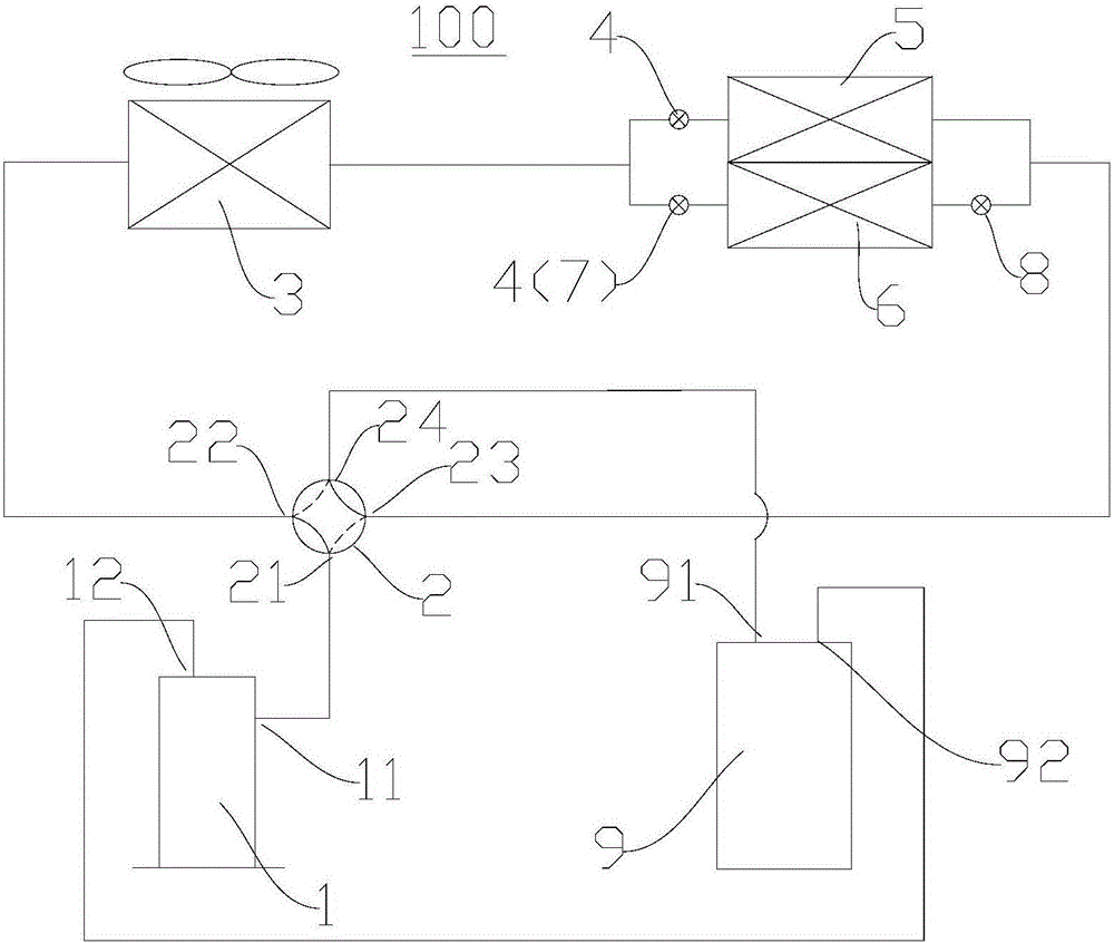
[0069] like image 3 As shown, the air conditioner 100 in this embodiment includes a compressor 1, a reversing assembly 2, an outdoor heat exchanger 3, two throttling elements 4, and a parallel-connected first indoor heat exchange set in the same indoor unit. 5 and the second indoor heat exchanger 6, the first control valve 7 and the second control valve 8. The second control valve 8 is a solenoid valve.

[0070] Specifically, the compressor 1 has an exhaust port 11 and an air return port 12. The reversing assembly 2 includes a first valve port 21 to a fourth valve port 24. When the air conditioner 100 is cooling, the first valve port 21 and the second valve port 22 The third valve port 23 communicates with the fourth valve port 24 , and the first valve port 21 communicates with the third valve port 23 and the second valve port 22 communicates with the fourth valve port 24 when the air conditioner 100 is heating. The first valve port 21 is connected to the exhaust port 11 , ...


PUM


Abstract

The invention discloses an air conditioner and a control method thereof. The air conditioner comprises a compressor, a reversing assembly, an outdoor heat exchanger, a throttling device, a first indoor heat exchanger, a second indoor heat exchanger, a first control valve and a second control valve, wherein the first indoor heat exchanger and the second indoor heat exchanger are arranged in the same indoor unit and connected in parallel; when the air conditioner is in a refrigeration mode and using of the second indoor heat exchanger needs to be stopped, the first control valve is closed, and the second control valve is in the state of blocking coolants from flowing towards the second indoor heat exchanger after a set period of time; and when the air conditioner is in a heating mode and using of the second indoor heat exchanger needs to be stopped, the heating mode is switched to be the refrigeration mode, then, the first control valve is closed, the refrigeration mode is switched to be the heating mode after a set period of time, and the second control valve is in the state of blocking the coolants from flowing towards the second indoor heat exchanger. According to the air conditioner provided by the invention, the problem that the heat exchange area of an indoor heat exchanger is too large can be solved, and the problem that the coolants are accumulated in a part of shielded indoor heat exchangers in the correlation technique is also solved.

Description

technical field [0001] The invention relates to the technical field of refrigeration equipment, in particular to an air conditioner and a control method for the air conditioner. Background technique [0002] When the indoor heat exchanger of the air conditioner is in heating operation, as the outdoor ambient temperature drops or the air conditioner is in partial load operation, the heat exchange area of ​​the indoor heat exchanger is too large, although the heat exchange effect of the heat exchanger is enhanced, But it also reduces the exhaust pressure of the compressor, and then reduces the return air pressure. The decrease of the return air pressure causes the refrigerant suction specific volume to increase, the density to decrease, and the corresponding refrigerant mass flow rate to decrease. At the same time, due to the decrease of the exhaust pressure of the refrigerant, the saturation pressure of the corresponding refrigerant decreases, which leads to a decrease in the...

Claims


Application Information

Patent Timeline
Patent Type & Authority Applications(China)
IPC IPC(8): F24F11/00F25B49/02F25B41/06F25B43/04F25B41/30
CPCF24F11/30F24F11/62F25B43/043F25B49/022F24F11/65F25B41/37
Inventor 李洪生许永锋梁伯启吴孔祥卢健洪肖俊钊邵亚西
Owner GD MIDEA HEATING & VENTILATING EQUIP CO LTD
Learn More