
Flanging punch

A technology of flanging and punching, which is applied in the field of pipe end forming and processing molds, can solve the problems of inability to perform simultaneous operations, complicated procedures, and low production efficiency.

Active Publication Date: 2016-10-12
苏州天朋精密元器件有限公司
View PDF5 Cites 0 Cited by
  • Summary
  • Abstract
  • Description
  • Claims
  • Application Information

AI Technical Summary

Problems solved by technology

Therefore, the deburring process needs to be processed in two strokes. Generally, the flanging operation is performed first, and then the deburring operation is performed. Since the two processes cannot be carried out at the same time, and the above method has complicated procedures and low production efficiency

Method used


Image

  • Flanging punch
  • Flanging punch

Examples


Embodiment Construction

[0019] The specific implementation manners of the present invention will be further described in detail below in conjunction with the accompanying drawings and embodiments. The following examples are used to illustrate the present invention, but are not intended to limit the scope of the present invention.

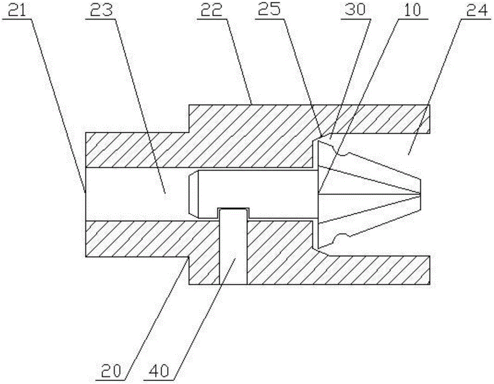
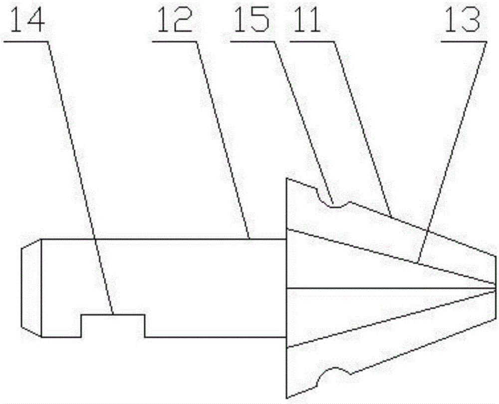
[0020] see figure 1 and figure 2 , a flanging punch described in a preferred embodiment of the present invention includes a flanging core 10, and a deburring jacket 20 is detachably connected to the flanging core 10. One end of the flanging mold core 10 is the flanging end 11, and the other end is the connecting end 12, and the flanging edge end 11 is in the shape of a cone whose diameter gradually increases toward the connecting end 12; the flanging mold core 10 is installed on the deburring In the inner hole 21 of the sheath 20 , one end of the deburring sheath 20 is a deburring end 22 , and there is a gap between the deburring end 22 and the burring end 11 . Wherein...


PUM


Abstract

The invention relates to a flanging punch which comprises a flanging mold core and a deburring jacket, wherein one end of the flanging mold core is the flanging end; the other end of the flanging mold core is the connecting end; the flanging end is in a conical shape with the diameter to be gradually increased towards the connecting end; collection grooves with the cross section to be semicircular are circumferentially formed in the outer wall of the flanging end, close to one end with the largest diameter; the deburring jacket is detachably connected with the flanging mold core; the flanging mold core is installed in an inner hole of the deburring jacket; one end of the deburring jacket is the deburring end; a gap is formed between the deburring end and the flanging end; the inner hole is a step hole with a first hole segment and a second hole segment; the inside diameter of the first hole segment is smaller than that of the second hole segment; the connecting end of the flanging mold core is installed in the first hole segment through a fastening part; the deburring end is formed at the second hole segment; and the second hole segment is provided with a chamber at the step.

Description

technical field [0001] The invention relates to the field of pipe end forming processing dies, in particular to a flanging punch. Background technique [0002] The quality of the copper pipe deburring nozzle has always been a bottleneck in the pipe end forming process. The quality of the processing directly affects the efficiency of the inner pipe and the upper quick connector. Since the current pipe end forming dies only have two types, the common flaring die and the shrinking die, there is no special deburring punch. [0003] In order to ensure the quality requirements of the upper quick connector and the inner piping, it is often necessary to deal with the burrs and the outer flanging problems at the same time to ensure the size requirements of the inner and outer diameters of the copper pipes. Therefore, the deburring process needs to be processed in two strokes. Generally, the flanging operation is performed first, and then the deburring operation is carried out. Becau...

Claims


Application Information

Patent Timeline
Patent Type & Authority Applications(China)
IPC IPC(8): B21D37/10B21D19/00B21D19/08
CPCB21D19/005B21D19/08B21D37/10
Inventor 付朝
Owner 苏州天朋精密元器件有限公司
Learn More