Lifting platform car capable of achieving height adjustment based on ball screw

A technology of lifting platform car and ball screw, which is applied in the direction of lifting device, etc., can solve the problems that the height of the ladder cannot be folded, the height of the platform device cannot be adjusted, and is fixed. Precise effect of lifting position

Inactive Publication Date: 2016-10-12
QINZHOU UNIV
View PDF11 Cites 4 Cited by
  • Summary
  • Abstract
  • Description
  • Claims
  • Application Information

AI Technical Summary

Problems solved by technology

At present, most of the high-altitude platform devices are ladders, such as Figure 4 As shown, including the platform, the ladders arranged under both sides of the platform, the ladder and the platform are arranged as a fixed structure or a foldable structure, the aerial operation platform of this structure has the following defects: the height of the platform device is not adjustable, fixed Unchanged, it is only suitable for work at a certain height, not suitable for work above or below this height, the scope of use is small, the practicability is poor, and the height of the ladder cannot be folded, especially the platform device with a higher height, It is bulky and difficult to transport and store; in addition, the platform device has steps on both sides, and there is no part that can move on the horizontal plane at the bottom. Generally, the horizontal shift is carried out by manual handling, which is laborious and slow in moving efficiency

Method used


Image

  • Lifting platform car capable of achieving height adjustment based on ball screw
  • Lifting platform car capable of achieving height adjustment based on ball screw
  • Lifting platform car capable of achieving height adjustment based on ball screw

Examples


Embodiment Construction

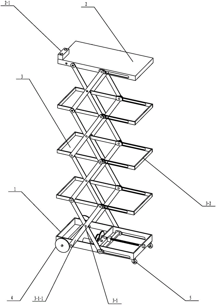
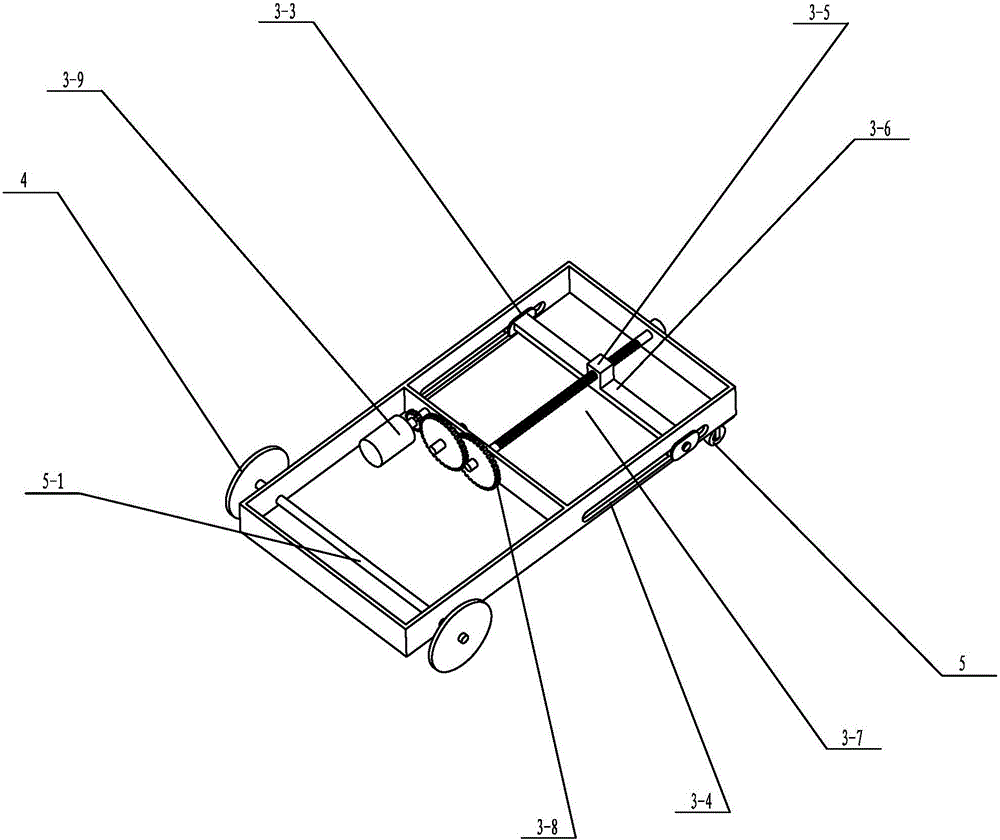
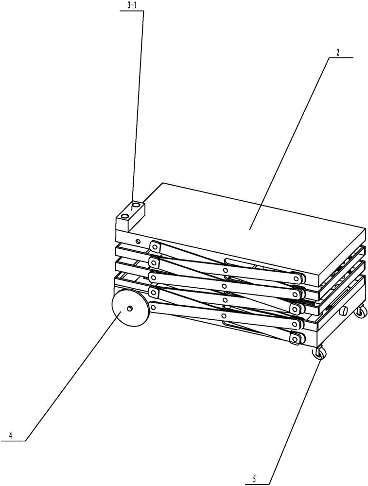
[0016] Such as figure 1 and figure 2 As shown, a specific embodiment of the present invention is proposed. The height-adjustable lifting platform vehicle based on a ball screw includes a chassis 1 and a lifting platform 2 arranged on the chassis 1. One end of the chassis 1 is symmetrically provided with rolling wheels 4 on both sides. , The bottom of both sides of the other end is symmetrically provided with universal wheels 5, and the two rolling wheels 4 are connected by a transmission shaft 4-1, and the chassis 1 and the lifting platform 2 are connected by a lifting assembly 3, and the lifting assembly 3 It includes several sets of lifting movable rod groups 3-1 symmetrically arranged on both sides between the lifting platform 2 and the chassis 1, and arranged up and down. The adjacent lifting movable rod groups 3-1 are hinged to each other, and the hinges are provided with lifting supports. Frame 3-2, the group of lifting movable rods 3-1 includes two movable rods 3-1-1...


PUM


Abstract

The invention discloses a lifting platform car capable of achieving height adjustment based on a ball screw. The lifting platform car comprises a chassis, and a lifting platform arranged on the chassis. Rolling wheels are symmetrically arranged on the two sides of one end of the chassis, and universal wheels are symmetrically arranged at the bottoms of the two sides of the other end of the chassis. The chassis is connected with the lifting platform through a lifting assembly. The lifting assembly comprises multiple sets of lifting movable rod sets symmetrically arranged on the two sides of the portion between a lifting plate and the chassis and arranged vertically. The adjacent lifting movable rod sets are hinged, and lifting supporting frames are arranged at the hinged positions. The two sides of the lifting plate, the two sides of the lifting supporting frame and the two sides of the chassis are each provided with a chute capable of allowing a sliding block to slide linearly. The lifting assembly is further provided with the ball screw, and a lifting switch is arranged on the lifting platform. The height of the lifting platform car can be flexibly adjusted, the lifting platform car can be suitable for aloft work at different heights, and the use range is wide; the lifting platform car can be folded and compressed, the size is reduced, carrying and storing are convenient, and the lifting platform car can conveniently move on the horizontal plane, and is good in practicality and worthy of being widely popularized.

Description

technical field [0001] The invention relates to a lifting platform, in particular to a lifting platform vehicle whose height is adjusted based on a ball screw. Background technique [0002] In life and production, it is often necessary to use high-altitude platform devices to complete some work, especially when painting and decorating walls. At present, most of the high-altitude platform devices are ladders, such as Figure 4 As shown, including the platform, the ladders arranged under both sides of the platform, the ladder and the platform are arranged as a fixed structure or a foldable structure, the aerial operation platform of this structure has the following defects: the height of the platform device is not adjustable, fixed Unchanged, it is only suitable for work at a certain height, not suitable for work above or below this height, the scope of use is small, the practicability is poor, and the height of the ladder cannot be folded, especially the platform device with ...

Claims


Application Information

Patent Timeline
Patent Type & Authority Applications(China)
IPC IPC(8): B66F11/04
CPCB66F11/042
Inventor 孙腾余观亮潘宇晨梁汉福
Owner QINZHOU UNIV
Why Eureka
Try Eureka