Lifting device for adjusting height based on ball screws

A technology for adjusting height and ball screw, applied in the direction of lifting device, lifting frame, etc., can solve the problems of unadjustable height of platform device, low work efficiency, non-foldable height of steps, etc., to achieve effective use of time, improve work efficiency, ensure Effects of device operation

Active Publication Date: 2016-10-26
QINZHOU UNIV
View PDF11 Cites 8 Cited by
  • Summary
  • Abstract
  • Description
  • Claims
  • Application Information

AI Technical Summary

Problems solved by technology

At present, most of the high-altitude platform devices are ladders, such as Image 6 As shown, including the platform, the ladders located under the two sides of the platform, the ladder and the platform are arranged as a fixed structure or a foldable structure, the aerial operation platform of this structure has the following defects: First, the height of the platform device is not enough Adjustable, fixed, only suitable for work at a certain height, not suitable for operations higher or lower than this height, the use range is small, the practicability is poor, and the height of the ladder cannot be folded, especially the higher height The platform device has a large volume and is difficult to transport and store; secondly, the platform device has steps on both sides, and there are no parts that can move on the horizontal plane at the bottom. If you need to change the horizontal position for work, you need to get off the platform and then It is troublesome and time-consuming to move the position of the platform device, resulting in low work efficiency

Method used


Image

  • Lifting device for adjusting height based on ball screws
  • Lifting device for adjusting height based on ball screws
  • Lifting device for adjusting height based on ball screws

Examples


Embodiment Construction

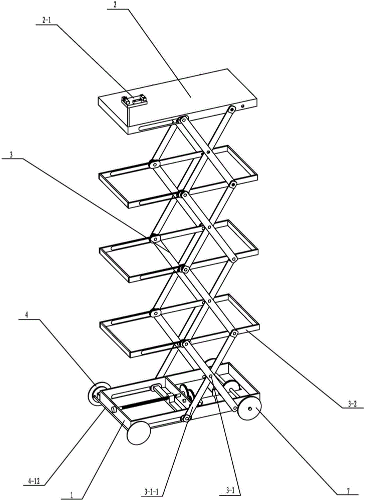
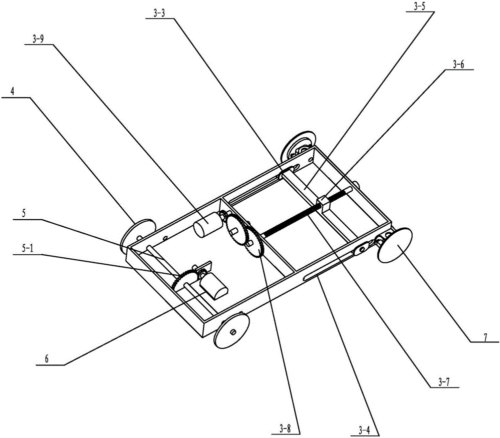
[0020] like figure 1 and figure 2 As shown, a specific embodiment of the present invention is proposed. The lifting device for height adjustment based on a ball screw includes a hollow chassis 1 and a lifting platform 2 arranged on the chassis 1. The lifting component is passed between the chassis 1 and the lifting platform 2. 3 connection, the lifting assembly 3 includes several sets of lifting movable rod groups 3-1 arranged symmetrically on both sides between the lifting platform 2 and the chassis 1, and arranged up and down, and the adjacent lifting movable rod groups 3-1 are hinged to each other , and the hinge is provided with a lifting support frame 3-2, the lifting movable rod 3-1 group includes two movable rods 3-1-1 hinged to each other into a cross structure, and the number of groups of the lifting assembly 3 can be adjusted according to the specific operating height Combined with the reasonable and reasonable setting of the length of the movable rod, generally t...


PUM


Abstract

The invention discloses a lifting device for adjusting a height based on ball screws. The lifting device comprises a chassis, and a lifting platform arranged on the chassis; the chassis and the lifting platform are connected through a lifting module; the lifting module includes multiple lifting movable rod sets symmetrically arranged on two sides between a lifting plate and the chassis up and down; the adjacent lifting movable rod sets are hinged with each other, and lifting support frames are arranged in the hinged places; chutes capable of linearly sliding slide blocks are formed in two sides of the lifting plate, the lifting support frames and the chassis; the ball screws are arranged on the lifting module; and a lifting switch is arranged on the lifting platform. The lifting device can flexibly adjust the height, can be suitable for aerial operations with different heights, is wide in application range, can fold and compress a lifting system and reduce the size to bring convenience for carrying, in addition, can move on the horizontal plane in all directions, saves both time and labors, is convenient and fast in adjustment, effectively improves the working efficiency, is convenient and practical, and deserves wide popularization.

Description

technical field [0001] The invention relates to a lifting platform, in particular to a lifting device for height adjustment based on a ball screw. Background technique [0002] In life and production, it is often necessary to use high-altitude platform devices to complete some work, especially when painting and decorating walls. At present, most of the high-altitude platform devices are ladders, such as Image 6 As shown, including the platform, the ladders located under the two sides of the platform, the ladder and the platform are arranged as a fixed structure or a foldable structure, the aerial operation platform of this structure has the following defects: First, the height of the platform device is not enough Adjustable, fixed, only suitable for work at a certain height, not suitable for operations higher or lower than this height, the scope of use is small, the practicability is poor, and the height of the ladder cannot be folded, especially the higher height The plat...

Claims


Application Information

Patent Timeline
Patent Type & Authority Applications(China)
IPC IPC(8): B66F7/06B66F7/28
CPCB66F7/0666B66F7/28
Inventor 孙腾余观亮潘宇晨梁汉福
Owner QINZHOU UNIV
Why Eureka
Try Eureka