Flanges capable of being positioned

A technology for positioning flanges and flanges. It is applied to flange connections, pipes/pipe joints/fittings, through components, etc. It can solve the problem of wasting manpower and material resources, and achieve the effect of stable positioning and connection.

Inactive Publication Date: 2016-10-12
SUZHOU COOBOS FLUID TECH
View PDF5 Cites 3 Cited by
  • Summary
  • Abstract
  • Description
  • Claims
  • Application Information

AI Technical Summary

Problems solved by technology

[0002] Flanges are parts that are connected to each other between shafts and are used for connection between pipe ends; they are also useful for flanges on equipment inlets and outlets for connection between two equipments. When two flanges are connected, it is necessary to First of all, to locate the two, two people are required, one for preliminary positioning, and the other for connection, which wastes manpower and material resources

Method used


Image

  • Flanges capable of being positioned
  • Flanges capable of being positioned
  • Flanges capable of being positioned

Examples


Embodiment 1

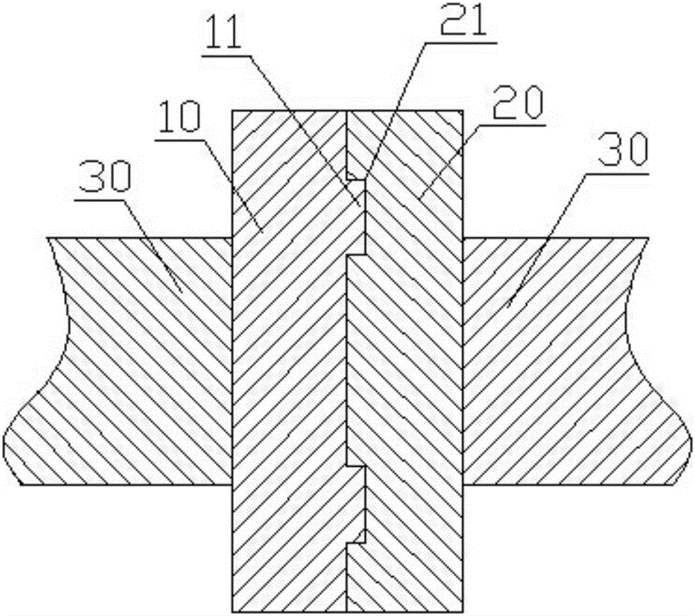
[0020] see figure 1 , as shown in the legend therein, a positionable flange includes a first flange 10 and a second flange 20 arranged left and right, the left end face of the first flange 10 and the left end of the second flange 20 The right end face is respectively connected with the pipeline 30, the right end face of the first flange 10 is protrudingly provided with a positioning protrusion 11, the left end face of the second flange 20 is concavely provided with a positioning groove 21, the first flange 10 The right end face of the second flange 20 is sealingly connected with the left end face of the second flange 20, and the positioning protrusion 11 is stuck in the positioning groove 21.

[0021] The positioning protrusion 11 is an annular protrusion, and the positioning groove 21 is an annular groove. The cross sections of the positioning protrusions 11 and the positioning grooves 21 are rectangular.

[0022] During assembly, preliminary positioning is performed throug...

Embodiment 2

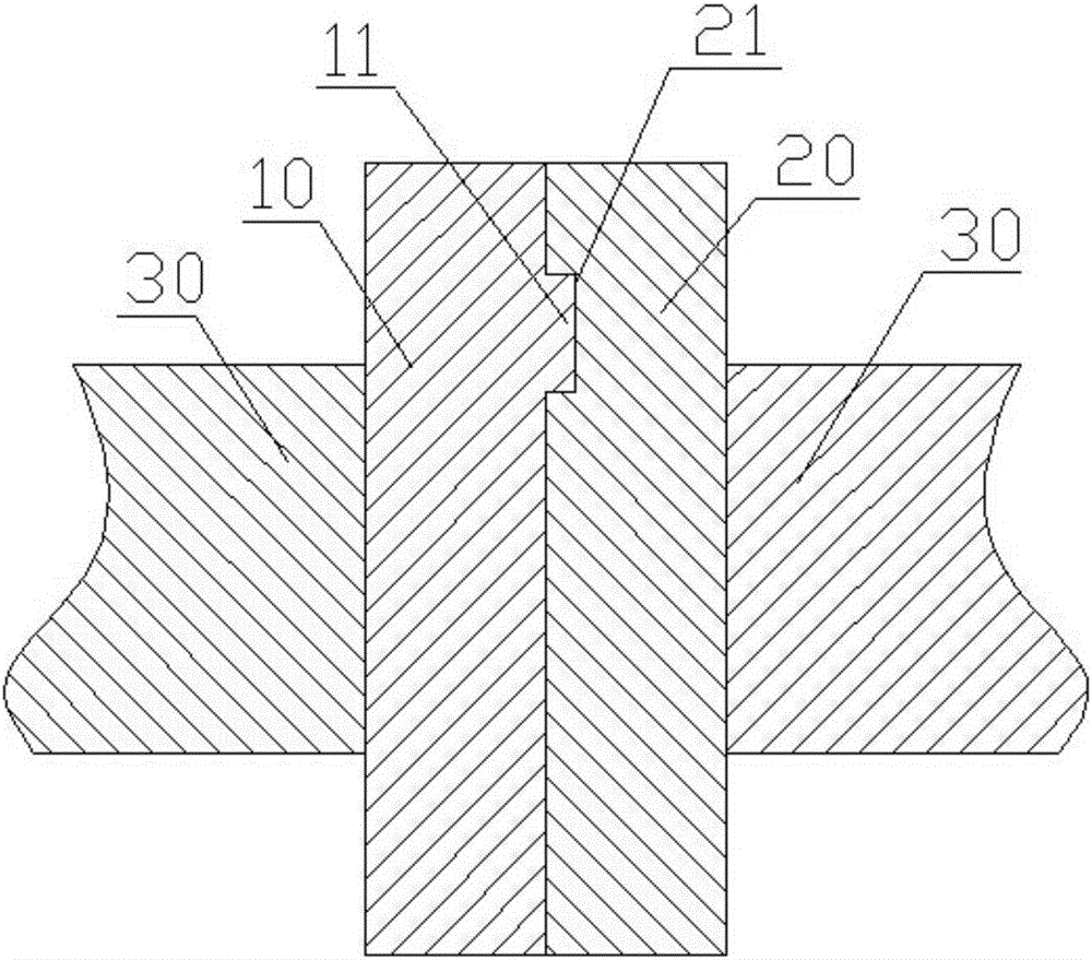
[0024] see figure 2 , as shown in the legend, the rest is the same as the first embodiment, the difference is that the positioning convex strip 11 is an arc-shaped convex strip, the positioning groove 21 is an arc-shaped groove, the arc-shaped convex strip is symmetrical front and back and passes through the first On the upper half of the flange 10 , the arc groove is symmetrical front and rear and passes through the upper half of the second flange 20 .

[0025] During assembly, preliminary positioning is performed through the positioning protrusions 11 and positioning grooves 21 , and then the connection between the first flange 20 and the second flange 21 is performed.

Embodiment 3

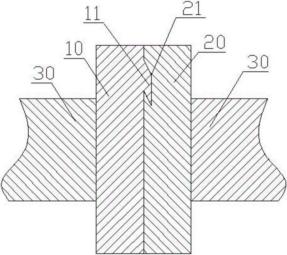
[0027] see image 3 , as shown in the legend, the rest is the same as the first embodiment, the difference is that the positioning convex strip 11 is a straight convex strip, the positioning groove 21 is a straight groove, the straight convex strip is symmetrical front and back and is located at the first On the upper half of the flange 10 , the arc-shaped groove is symmetrical front and rear and is located on the upper half of the second flange 20 . The cross sections of the positioning protrusions 11 and the positioning grooves 21 are parallelograms.

[0028] During assembly, the second flange 20 is assembled first, and then the first flange 10 is positioned on the second flange 20 .


PUM


Abstract

The invention discloses flanges capable of being positioned. The flanges comprise a first flange plate and a second flange plate which are arranged left and right; the left end surface of the first flange plate and the right end surface of the second flange plate are connected with pipelines correspondingly; the right end surface of the first flange plate is convex and provided with positioning convex strips; the left end surface of the second flange plate is concave and provided with positioning concave grooves; the right end surface of the first flange plate is in sealing connection with the left end surface of the second flange plate; and the positioning convex strips are clamped in the positioning concave grooves. According to the flanges capable of being positioned, the two flange plates are provided with the convex strips and the concave grooves, so that the two flange plates are preliminarily positioned and are assembled by one person.

Description

technical field [0001] The invention relates to the field of pipeline systems, in particular to a positionable flange. Background technique [0002] Flanges are parts that are connected to each other between shafts and are used for connection between pipe ends; they are also useful for flanges on equipment inlets and outlets for connection between two equipments. When two flanges are connected, it is necessary to First of all, two people are required to locate the two, one for preliminary positioning and the other for connection, which wastes manpower and material resources. Contents of the invention [0003] In order to solve the above technical problems, the purpose of the present invention is to provide a positionable flange, which can be positioned by itself when connecting two flanges, and one person can connect the two flanges. [0004] In order to achieve the purpose of the above invention, the present invention provides the following technical solutions: a positio...

Claims


Application Information

Patent Timeline
Patent Type & Authority Applications(China)
IPC IPC(8): F16L23/00
CPCF16L23/00
Inventor 朱洪斌周晓斌
Owner SUZHOU COOBOS FLUID TECH
Why Eureka
Try Eureka