Surface-attached type three-phase permanent magnet synchronous motor rotor magnetic pole initial position location method

A permanent magnet synchronous motor and rotor magnetic pole technology, which is applied in the control of generators, motor generators, and electromechanical transmissions, etc., and can solve the problems of low positioning accuracy and long positioning time.

Active Publication Date: 2018-05-01
杭州量创科技咨询有限公司
View PDF10 Cites 2 Cited by
  • Summary
  • Abstract
  • Description
  • Claims
  • Application Information

AI Technical Summary

Problems solved by technology

[0004] The purpose of the present invention is to solve the problems of long positioning time and low positioning accuracy of the existing three-phase permanent magnet synchronous motor rotor magnetic pole position initial positioning method, and to provide a surface-mounted three-phase permanent magnet synchronous motor rotor magnetic pole initial position positioning method. The method can effectively and quickly realize the initial positioning of the rotor magnetic pole position of the three-phase permanent magnet synchronous motor, and provide an effective starting position signal for the initial positioning of the motor encoderless control or incremental encoder

Method used


Image

  • Surface-attached type three-phase permanent magnet synchronous motor rotor magnetic pole initial position location method
  • Surface-attached type three-phase permanent magnet synchronous motor rotor magnetic pole initial position location method
  • Surface-attached type three-phase permanent magnet synchronous motor rotor magnetic pole initial position location method

Examples


Embodiment

[0026] Embodiment: A method for locating the initial position of the rotor magnetic pole of a surface-mounted three-phase permanent magnet synchronous motor. This method comprises the following steps:

[0027] Step 1: PWM period T PWM determination;

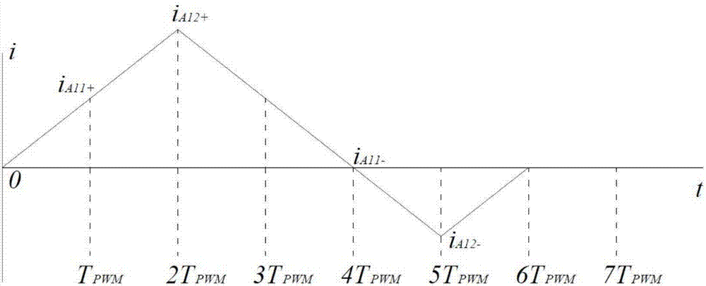
[0028] The PWM period is initialized as Run the motor for PWM control: where, Input the voltage vector whose electrical angle is 0°, For the PWM full off state, Input the voltage vector whose electrical angle is 180°, For the PWM full shutdown state, the The current value of phase A is collected at all times and recorded as at a duration of When the PWM control ends, if the is less than the rated current peak value of the motor, then gradually increase the PWM period, so that p=1, 2, 3..., k is the increment of the PWM cycle, and the duration of the motor is PWM control, acquisition of and judge as a function of the peak value of the rated motor current, up to Equal to or greater than the peak value ...


PUM


Abstract

The invention relates to a surface-attached type three-phase permanent magnet synchronous motor rotor magnetic pole initial position location method, which solves the problem that the existing three-phase permanent magnet synchronous motor rotor magnetic pole position initial position location method is contradiction between the location time and the location precision. According to the method, only six basic spatial voltage vectors are injected to a three-phase permanent magnet synchronous motor in a static state; a PWM full-turn-off state for switch of the voltage vectors is used as switching buffer of adjacent voltage vectors, so that the dead zone time does not need to be configured for the PWM output signal, and only the phase current response value is acquired; the variable quantityrelated to the trigonometric function of the initial position angle of the rotor magnetic pole is constructed; and the initial position of the rotor magnetic pole can be detected through calculation of the inverse trigonometric function. According to the surface-attached type three-phase permanent magnet synchronous motor rotor magnetic pole initial position location method, complicated high-frequency voltage injection or sequence pulse voltage injection is not needed, the implementation is simple, and the location speed is high; and only six basic voltage vectors are used, so that rapid and high-precision location of the initial position of the rotor magnetic pole can be achieved.

Description

technical field [0001] The invention belongs to the field of motors, and relates to a motor control method, in particular to a method for locating the initial position of a rotor magnetic pole of a surface-mounted three-phase permanent magnet synchronous motor. Background technique [0002] The three-phase permanent magnet synchronous motor has the characteristics of high power density, convenient control, and good control performance. However, when the motor is started, it is necessary to know the initial position of the motor rotor magnetic poles, otherwise it will fail to start. Therefore, encoders are generally used to detect the position of the motor rotor magnetic poles. Absolute encoders or incremental encoders with UVW can solve the problem of motor Start-up problem, but it brings an increase in cost, and the incremental encoder with UVW, the initial positioning accuracy of the magnetic pole is only + / -30° electrical angle. [0003] The traditional three-phase perma...

Claims


Application Information

Patent Timeline
Patent Type & Authority Applications(China)
IPC IPC(8): H02P21/18H02P21/32
Inventor 王立强雷美珍
Owner 杭州量创科技咨询有限公司
Why Eureka
Try Eureka