Assembly die base and production technology thereof

A production process and assembly technology, applied in the direction of metal material coating process, coating, solid diffusion coating, etc., can solve the problems of gaps between A board and B board, mold cavity damage, impurity entry, etc., to avoid the level Offset, strong wear resistance, and life-enhancing effects

Active Publication Date: 2020-01-24
厦门东抚工贸有限公司
View PDF11 Cites 2 Cited by
  • Summary
  • Abstract
  • Description
  • Claims
  • Application Information

AI Technical Summary

Problems solved by technology

[0004] However, during the transportation of the existing formwork, there is often a gap between the A board and the B board due to vibration or other reasons, and once there is a gap between the A board and the B board, impurities will enter the mold cavity. Causes mold cavity damage, so there is room for improvement

Method used


Image

  • Assembly die base and production technology thereof
  • Assembly die base and production technology thereof
  • Assembly die base and production technology thereof

Examples


Embodiment Construction

[0045] The present invention will be described in further detail below in conjunction with the accompanying drawings.

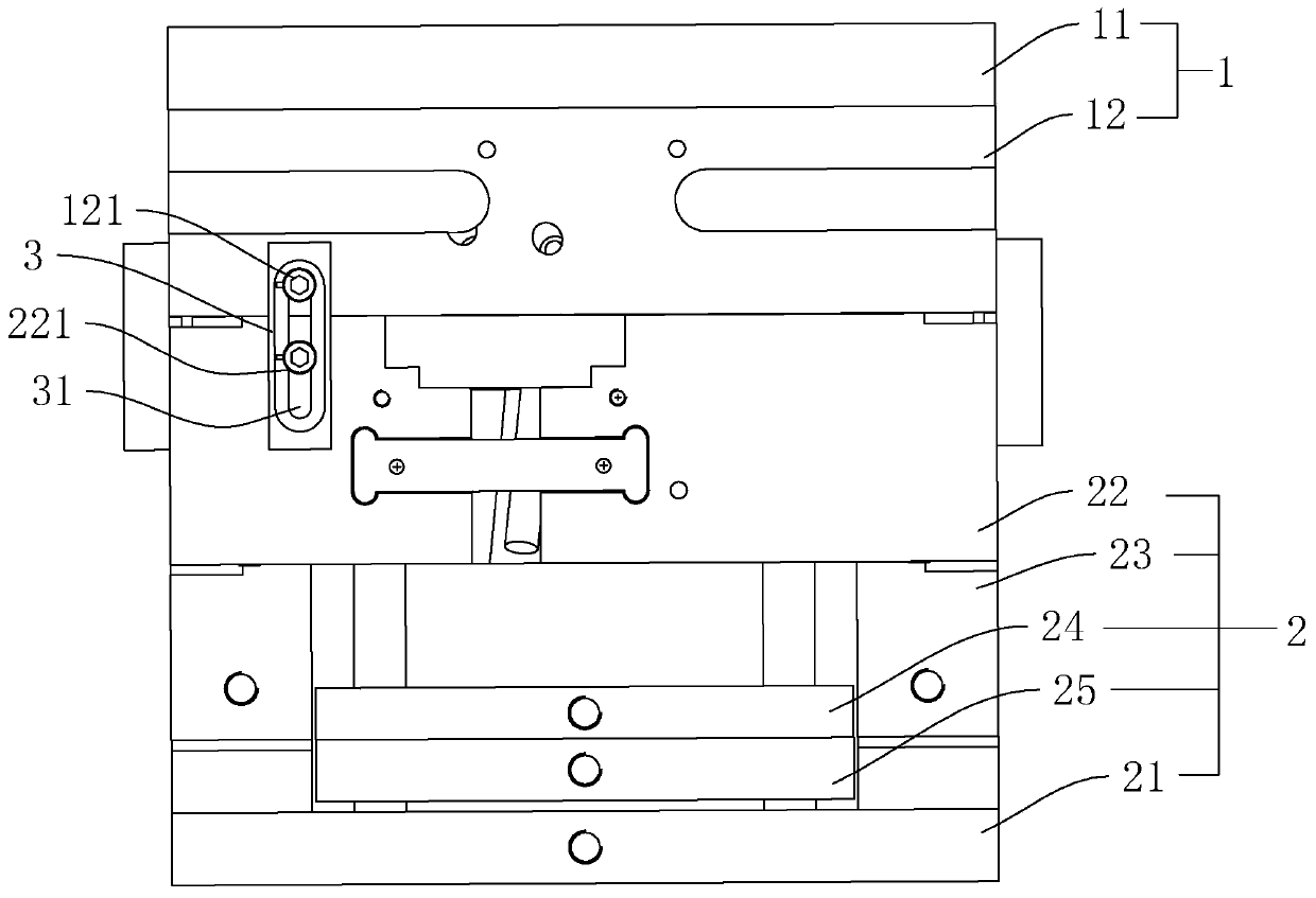
[0046] An assembled formwork such as figure 1Shown, comprise upper mold 1 and lower mold 2, upper mold 1 comprises panel 11 and the A board 12 that is installed on the lower surface of panel 11, lower mold 2 comprises bottom plate 21, B board 22, square iron 23, needle face plate 24 and Bottom needle plate 25, face needle plate 24 and bottom needle plate 25 are located in the area surrounded by base plate 21, square iron 23 and B plate 22.

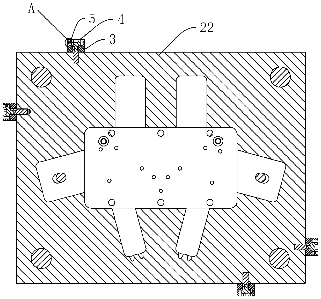
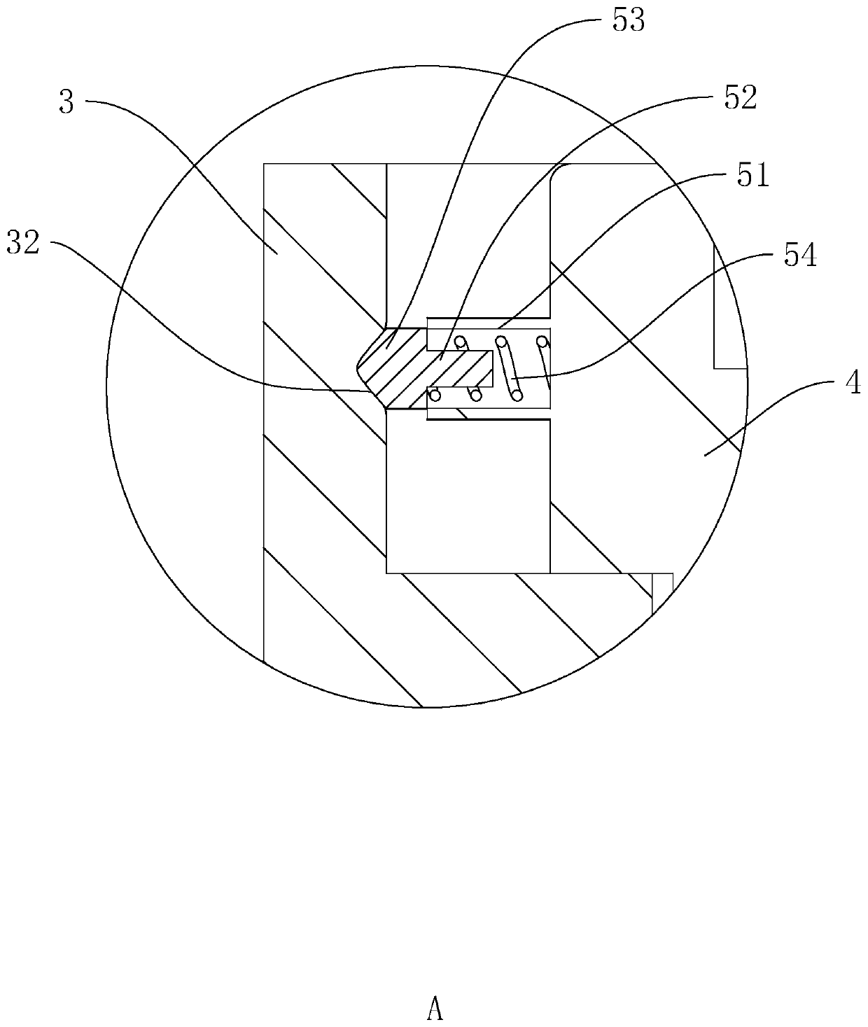
[0047] Such as figure 1 , 2 As shown, four lock modules 3 connecting the A board 12 and the B board 22 are arranged between the upper mold 1 and the lower mold 2. The four lock modules 3 are distributed on the four sides of the A board 12, and the lock modules 3 are fixed on the A board. On the outer wall of the plate 12. Wherein, each lock module 3 is provided with a chute 31 in the vertical direction, and the A plat...


PUM


Abstract

The invention discloses an assembly die base and a production technology thereof and belongs to the technical field of injection model machining. According to the technical scheme, the assembly die base is characterized by comprising an upper die and a lower die; the upper die comprises a face plate and a plate A arranged on the lower surface of the face plate; the lower die comprises a bottom plate, a plate B, square iron, a face needle plate and a bottom needle plate; at least one die locking block connected with the plate A and the plate B is arranged between the upper die and the lower die; the die locking blocks are fixed to the outer side of the plate A or the plate B; a sliding groove is formed in each die locking block in the vertical direction, wherein a limiting pin A and a limiting pin B sliding in the sliding groove are arranged on the plate A and the plate B correspondingly; limiting caps are rotationally arranged on the limiting pins A and the limiting pins B; elastic clamping parts are connected to one sides of the limiting caps; and clamping connecting grooves for the elastic clamping parts to be embedded are formed in the die locking blocks. The assembly die base and the production technology thereof have the beneficial effect that the plate A and the plate B can be attached to each other tightly in the transportation process, and completeness of a die cavity is ensured.

Description

technical field [0001] The invention belongs to the technical field of injection mold processing, and more specifically relates to an assembled formwork and its production process. Background technique [0002] The mold base is the support of the mold, which is used to combine and fix the parts of the mold according to certain rules and positions, and then install them on injection molding machines, die-casting machines, extrusion machines and other workpiece processing equipment for work. The application fields of mold bases involve, for example, Automobile, aerospace, daily necessities, electrical communication, medical products and equipment and many other industries. [0003] In the prior art, the die-casting formwork generally includes an upper mold and a lower mold, and the lower mold includes a base plate, a B plate, a face needle plate and a bottom needle plate, the B plate is installed on the base plate, and the face needle plate and the bottom needle plate are inst...

Claims


Application Information

Patent Timeline
Patent Type & Authority Applications(China)
IPC IPC(8): B29C45/17B23P15/00C23C12/00C21D1/18
CPCB29C45/1742B23P15/007C23C12/00C21D1/18
Inventor 陈建军
Owner 厦门东抚工贸有限公司
Why Eureka
Try Eureka