
Anti-blocking type projection system

A projection system and projector technology, applied in optics, instruments, projection devices, etc., can solve the problem of portable projector light being easily blocked by obstacles, and achieve the effect of achieving high projection height and easy portability

Active Publication Date: 2016-11-09
CHENGDU ZHIRONG ZHICHUANG INTPROP MANAGEMENT CO LTD
View PDF14 Cites 0 Cited by
  • Summary
  • Abstract
  • Description
  • Claims
  • Application Information

AI Technical Summary

Problems solved by technology

[0006] The purpose of the present invention is to provide an anti-blocking projection system, which solves the problem that the existing fixing device guide is not suitable for portable projectors, and part of the light emitted by the projector is easily blocked by obstacles. At the same time, the projector body described in the present invention height adjustable

Method used


Image

  • Anti-blocking type projection system
  • Anti-blocking type projection system

Examples


Embodiment 1

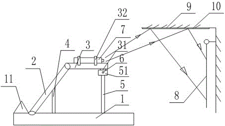
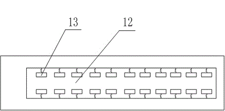
[0034] Such as figure 1 , figure 2 As shown, the anti-blocking projection system includes a projector body 7 and a projection screen 8 installed on a corresponding wall, a reflective glass 10 is arranged on the ceiling 9 between the projector body 7 and the projection screen 8, and the projection The instrument body 7 is arranged on a fixing mechanism, and the fixing mechanism includes a base plate 1, the upper end surface of the base plate 1 is hinged with a side plate 2, and the end of the side plate 2 is hinged with a horizontal plate 3, and the upper end surface of the base plate 1 is provided with The first piston rod 4 that cooperates with the side plate 2 and the second piston rod 5 that cooperates with the horizontal plate 3, the first piston rod 4 and the second piston rod 5 are arranged in the slot 12 provided on the upper end surface of the bottom plate 1, The two symmetrical side walls of the draw-in groove 12 are provided with a plurality of springs, the non-fix...

Embodiment 2

[0036] Such as figure 1 , figure 2 As shown, this embodiment is based on Embodiment 1. The upper end surface of the bottom plate 1 is provided with a limit plate 11 that cooperates with the side plate 2; the lower end surface of the horizontal plate 3 is provided with a bump 31 on which There is a threaded through hole, the upper end of the second piston rod 5 is provided with a U-shaped plate 51, and the two side walls of the U-shaped plate 51 are provided with a threaded through hole I that matches the threaded through hole, and the bolt 6 passes through the threaded through hole. The hole I and the threaded through hole realize the fixed connection between the U-shaped plate 51 and the bump 31; the upper end surface of the horizontal plate 3 is provided with a groove for clamping the projector body 7, and the inner wall of the groove is set as a threaded surface The horizontal plate 3 is provided with a fixing bar 32 for pressing and fixing the projector body 7; the fixin...


PUM


Abstract

The invention discloses an anti-blocking type projection system which includes a projector body and a projection curtain installed on a corresponding wall. Reflecting glass is arranged on a ceiling between the projector body and the projection curtain. The projector body is arranged on a fixing mechanism which comprises a bottom plate. A side plate is hinged with an upper end surface of the bottom plate. A transverse plate is hinged with an end portion of the side plate. The upper end surface of the bottom plate is provided with a first piston rod matched with the side plate, and a second piston rod matched with the transverse plate. The first piston rod and the second piston rod are arranged in a channel section arranged in the upper end surface of the bottom plate. A plurality of springs are arranged on two symmetrical side walls of the channel sections. Non-fixing ends of the springs are connected to clamping blocks. The springs on the two symmetrical side walls are arranged symmetrically. The anti-blocking type projection system solves the problems that existing fixing devices are not suitable for portable projectors and one part of the light emitted from the projectors is easily blocked by obstacles. Meanwhile, the height of the projector body can be adjusted.

Description

technical field [0001] The invention relates to the technical field of projection equipment, in particular to an anti-blocking projection system. Background technique [0002] Projectors are also known as projectors. At present, projection technology is changing with each passing day. With the development of science and technology, the projection industry has also developed into a field with the highest micro-projection technology. [0003] The projector is a precision electronic product, which integrates machinery, liquid crystal or DMD, and electronic circuits, so it must be carefully protected during use, especially to prevent it from being impacted. [0004] The projector needs to be fixed by a fixing device during use, which is not suitable for portable projectors. [0005] Moreover, in the existing projection system, part of the light emitted by the projector is easily blocked by obstacles, and a complete image cannot be seen. Contents of the invention [0006] The...

Claims


Application Information

Patent Timeline
Patent Type & Authority Applications(China)
IPC IPC(8): G03B21/28G03B21/54
CPCG03B21/28G03B21/54
Inventor 谢义刚
Owner CHENGDU ZHIRONG ZHICHUANG INTPROP MANAGEMENT CO LTD
Learn More