
Projector fixing device

A technology for fixing devices and projectors, applied in projection devices, instruments, optics, etc., can solve the problems of not being suitable for portable projectors, etc., and achieve the effect of being easy to carry

Inactive Publication Date: 2016-12-21
成都西华升腾科技有限公司
View PDF4 Cites 1 Cited by
  • Summary
  • Abstract
  • Description
  • Claims
  • Application Information

AI Technical Summary

Problems solved by technology

[0005] The object of the present invention is to provide a projector fixing device to solve the problem that the existing fixing devices are not suitable for portable projectors

Method used


Image

  • Projector fixing device

Examples


Embodiment 1

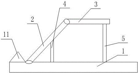
[0027] Such as figure 1 As shown, a projector fixing device includes a base plate 1, the upper end surface of the base plate 1 is hinged with a side plate 2, the end of the side plate 2 is hinged with a horizontal plate 3, and the upper end surface of the base plate 1 is provided with a first clip slot and the second slot, the lower end surface of the side plate 2 is provided with a third slot matching the first slot, and the lower end surface of the horizontal plate 3 is provided with a fourth slot matching the second slot , the bottoms of the first card slot, the second card slot, the third card slot and the fourth card slot are all provided with elastic members, and the first connecting rod 4 is arranged between the first card slot and the third card slot , a second connecting rod 5 is arranged between the second card slot and the fourth card slot.

Embodiment 2

[0029] Such as figure 1 As shown, this embodiment is based on Embodiment 1. The upper end surface of the bottom plate 1 is provided with a limit plate 11 that cooperates with the side plate 2; the elastic member is a spring; A groove for the projector is provided; the inner wall of the groove is set as a threaded surface.


PUM


Abstract

The invention discloses a projector fixing device. The projector fixing device comprises a bottom plate. A side plate is hinged to the upper end face of the bottom plate. A transverse plate is hinged to the end portion of the side plate. A first clamping groove and a second clamping groove are formed in the upper end face of the bottom plate. A third clamping groove matched with the first clamping groove is formed in the lower end face of the side plate. A fourth clamping groove matched with the second clamping groove is formed in the lower end face of the transverse plate. Elastic pieces are arranged at the bottoms of the first clamping groove, the second clamping groove, the third clamping groove and the fourth clamping groove. A first connecting rod is arranged between the first clamping groove and the third clamping groove, and a second connecting rod is arranged between the second clamping groove and the fourth clamping groove. According to the projector fixing device, the transverse plate and the side plate which are hinged to each other are arranged, and the side plate is hinged to the bottom plate so that the transverse plate and the side plate can be stored and released; when the projector fixing device needs to be used, the first connecting rod and the second connecting rod are used for conducting fixing; and when the projector fixing device does not need to be used, the first connecting rod and the second connecting rod are detached, and carrying is convenient.

Description

technical field [0001] The invention relates to the technical field of projection equipment, in particular to a projector fixing device. Background technique [0002] Projectors are also known as projectors. At present, projection technology is changing with each passing day. With the development of science and technology, the projection industry has also developed into a field with the highest micro-projection technology. [0003] The projector is a precision electronic product, which integrates machinery, liquid crystal or DMD, and electronic circuits, so it must be carefully protected during use, especially to prevent it from being impacted. [0004] The projector needs to be fixed by a fixing device during use, which is not suitable for portable projectors. Contents of the invention [0005] The purpose of the present invention is to provide a projector fixing device to solve the problem that the existing fixing device is not suitable for portable projectors. [0006...

Claims


Application Information

Patent Timeline
IPC IPC(8): F16M11/00G03B21/54
CPCF16M11/00G03B21/54
Inventor 谢义刚
Owner 成都西华升腾科技有限公司
Learn More