Object tracking system and object tracking method in camera-distributed map

A technology of distribution map and target tracking, applied in the field of target tracking system, can solve problems such as heavy workload and complexity

Active Publication Date: 2016-11-09
徐州汉泽信息科技有限公司
View PDF7 Cites 48 Cited by
  • Summary
  • Abstract
  • Description
  • Claims
  • Application Information

AI Technical Summary

Problems solved by technology

Although this application can also achieve the purpose of intelligent monitoring to a certain extent, in view of the fact that the effective clips of the target appearing in the video only account for a small proportion of the monitoring staff's screen-browsing workload, and if it is necessary to rely on manual The camera monitoring node draws a path on the ma

Method used


Image

  • Object tracking system and object tracking method in camera-distributed map
  • Object tracking system and object tracking method in camera-distributed map
  • Object tracking system and object tracking method in camera-distributed map

Examples


Embodiment 1

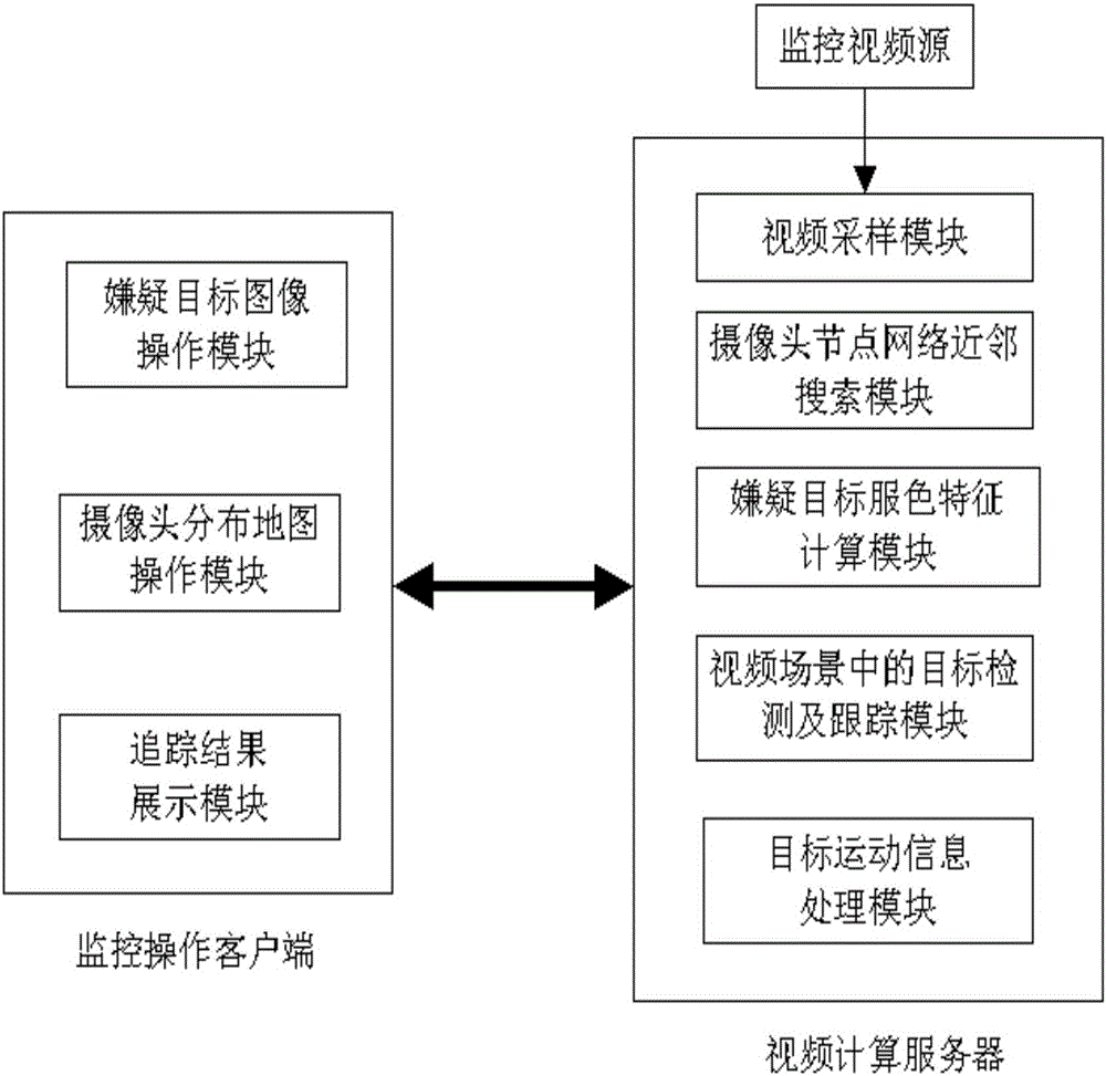
[0047] combine figure 1 In this embodiment, a target tracking system in a camera distribution map includes two parts: a monitoring operation client and a video computing server.

[0048] The monitoring operation client includes a suspect target image operation module, a camera distribution map operation module and a tracking result display module. The camera nodes in the monitoring area have already been marked on the map through the GIS API interface, and have the function of calling the monitoring video information on the corresponding camera node.

[0049] The suspect target image operation module mainly realizes that when the suspect target is not found in the monitoring area, directly import the suspect target image; or when the suspect target is found in the monitoring area, select the video frame containing the suspect target, and interact with the mouse The function of delineating and delineating the suspected target and the area where it is located.

[0050] The cam...

Embodiment 2

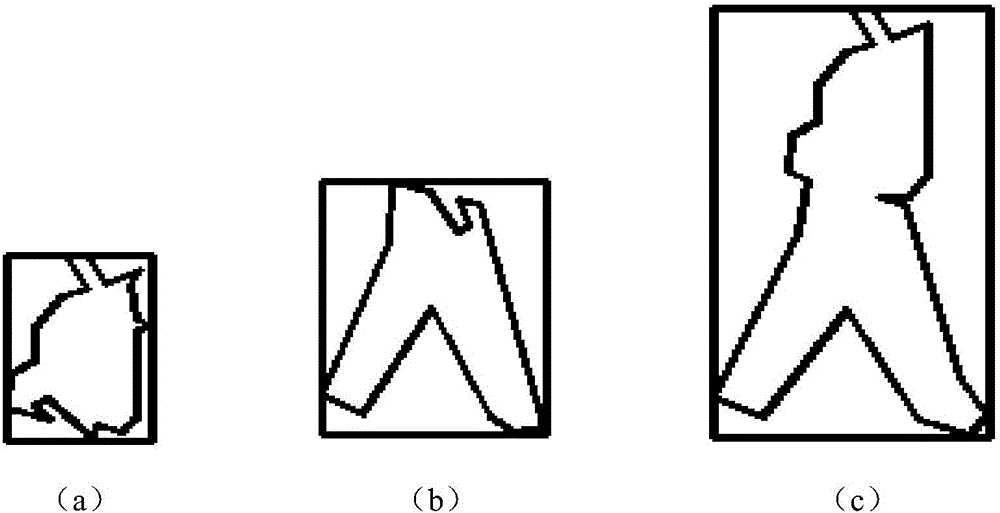
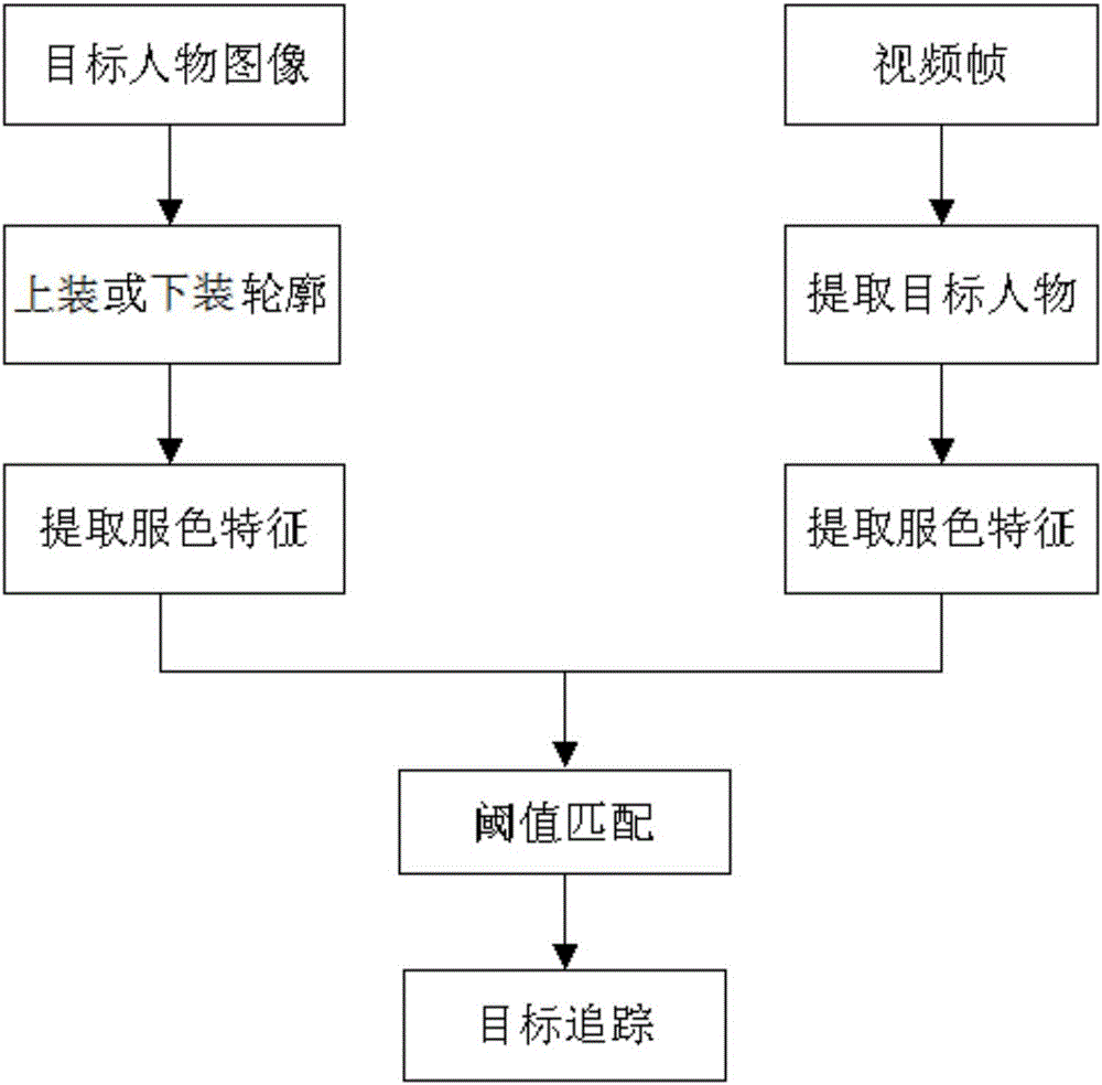
[0070] The object tracking system and tracking method in a camera distribution map of this embodiment are basically the same as in Embodiment 1, the difference is that in this embodiment, the clothing color of the suspect's bottom clothing is fused as the clothing color feature template of the suspect, For example, the main color of the bottom of the suspect target is blue, and only the area containing blue is segmented by the back projection method, and the boundary of the bottom of the suspect target is segmented, such as figure 2 As shown in (b), when the region growing method is used, the seed point is the centroid of the lower half of the image of the imported suspected target, and the core value of the principal component of the color histogram in the boundary area is calculated as the feature template.

Embodiment 3

[0072] The target tracking system and tracking method in a camera distribution map of this embodiment are basically the same as in Embodiment 1, the difference is that in this embodiment, the color fusion of the upper and lower clothing of the suspect target is selected as the clothing of the suspect target. Color feature templates, such as figure 2 As shown in (c), that is, in this embodiment, the image containing only the upper body and the lower garment area processed by the region growing method is subjected to array weighted fusion, and the fusion formula is as follows:

[0073] g(x)=(1-α)f 0 (x)+αf 1 (x)

[0074] In this embodiment, the value of α is 0.5, and f 0 (x) and f 1 (x) respectively represent the image arrays of the upper body and the lower body after processing by the region growing method.


PUM


Abstract

The invention discloses an objective tracking system and an objective tracking method in a camera-distributed map. The object tracking system comprises a monitoring operation client and a video calculating server. The monitoring operation client inputs an image of a suspected object and sets a to-be-searched range through the camera-distributed map. The video calculating server performs processing on a video and an image which are obtained through sampling. The object tracking method comprises the steps of extracting color characteristic of the image of the suspected target, detecting and tracking the target in a video scene, recording motion information of the target, and then transmitting a corresponding calculating result to the monitoring operation client; on the map in which camera nodes are marked by the monitoring operation client, acquiring the path track of the suspected object on the map according to the camera nodes where the suspected object appears, and simultaneously collecting information such as advancing speed and state of the target, thereby facilitating analysis by safety monitoring personnel. The objective tracking system and the objective tracking method have advantages of greatly reducing work difficulty in observing a screen for searching, making personnel concentrate on effective video segments, and realizing relatively high application value at a scientific police improvement aspect.

Description

technical field [0001] The invention belongs to the technical field of video surveillance, and more specifically relates to a target tracking system and tracking method in a camera distribution map. Background technique [0002] With the improvement of the requirements for smart cities, people's demand for video surveillance is unprecedentedly high, and the cameras deployed in various places are becoming more and more dense. There are at least 10 million surveillance cameras used in urban surveillance and alarm systems in our country. Although the addition of cameras has brought benefits to large-scale prevention and the ability to obtain massive amounts of video data for real-time alarms and post-event inquiries, how to use massive amounts of video data manually has become a huge challenge. The Sandia National Laboratory in the United States conducted a special study, and the results showed that if a person stares intently at a large number of video images, after only 22 m...

Claims


Application Information

Patent Timeline
IPC IPC(8): G06K9/00
CPCG06V20/42G06V20/46
Inventor 纪滨许婷申元霞粱昌龙
Owner 徐州汉泽信息科技有限公司
Why Eureka
Try Eureka