Span device wire clamp for connecting electric power conductor and electric power device

A technology for power equipment and power wires, applied in conductive connection, electrical component connection, connection, etc., can solve the problems of users' delay in power transmission, large connection resistance, long connection time, etc., to achieve good connection effect and small inventory. , the effect of good versatility

Active Publication Date: 2016-11-09
郭金泉
View PDF4 Cites 5 Cited by
  • Summary
  • Abstract
  • Description
  • Claims
  • Application Information

AI Technical Summary

Problems solved by technology

[0002] At present, there are many shortcomings and deficiencies in the commonly used power equipment clamps. These shortcomings and deficiencies are mainly manifested in the following aspects: 1. The bolt fastening connection is a rigid connection, and its connection resistance is large, and accidents of burns and disconnection occur from time to time; 2. Although the connection effect of hydraulic connection and mechanical crimping is good, it not only requires a variety of expensive special tools, but also takes a long time to connect, which often affects many users' delay in power transmission; 3. The specifications of the equipment clamps currently used , There are dozens of varieties, procurement and picking are prone to errors, there are many types of storage, large inventory, and high cost

Method used


Image

  • Span device wire clamp for connecting electric power conductor and electric power device
  • Span device wire clamp for connecting electric power conductor and electric power device
  • Span device wire clamp for connecting electric power conductor and electric power device

Examples


Embodiment Construction

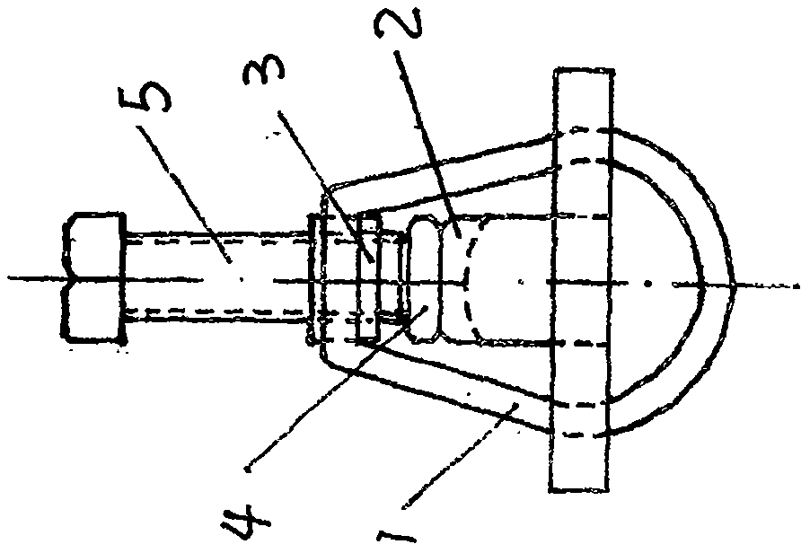
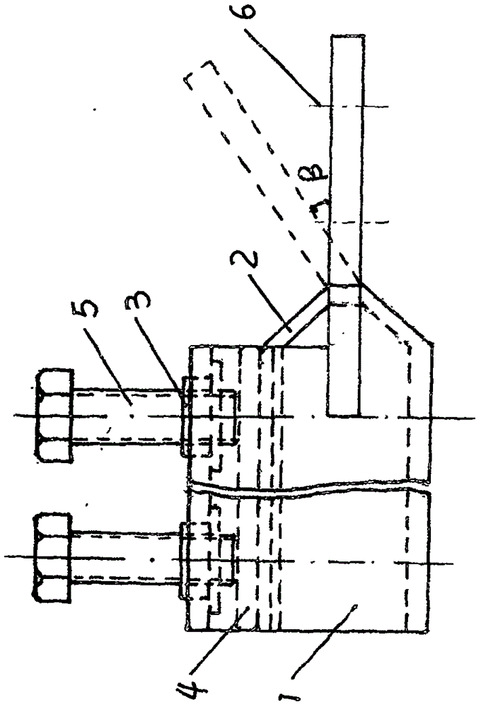
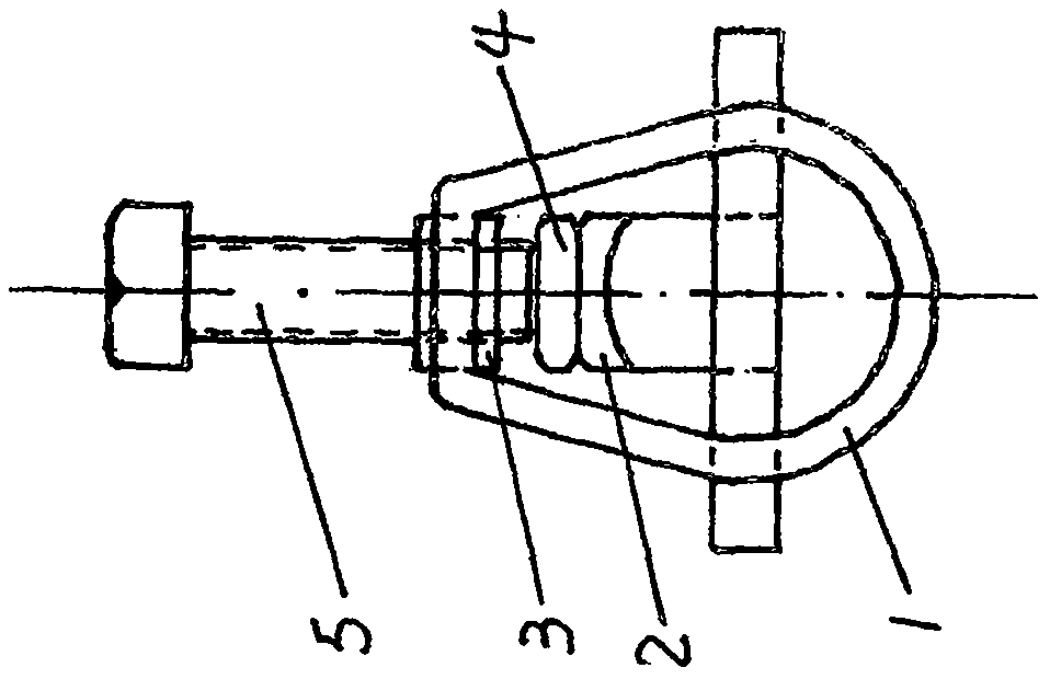
[0028] Figures 1 to 6 As shown in and 11: the span equipment clamp for connecting the power conductor to the power equipment is mainly composed of a threading pipe 1 and a fastening bolt 5. The front part of the threading pipe 1 is a threading pipe body, and the threading pipe body of the threading pipe 1 The rear part of the threading pipe 1 is provided with a connection fixing plate fixedly connected with the threading pipe body, and the installation fixing hole 6 connected with the terminal post of the external electric equipment is arranged on the connection fixing plate. The cross section of the threading pipe body at the front part of the threading pipe 1 is An elliptical ring body with a flat top at the top, a semicircular cavity at the bottom of the elliptical ring body, and a trapezoidal cavity at the top of the elliptical ring body, the fastening bolts 5 are vertically arranged and screwed In the trimming flange nut on the upper top of the trapezoidal cavity, a clam...


PUM


Abstract

The invention discloses a span device wire clamp for connecting an electric power conductor and an electric power device. The span device wire clamp consists of a wire threading tube and a fastening screw bolt, wherein a front end of the wire threading tube is a wire threading tube body, a rear part of the wire threading tube body is provided with a connection fixing plate, the connection fixing plate is provided with an installation fixing hole connected with a wire connecting post of an external electric power device, a cross section of the wire threading tube body is shaped like an oval ring body of which an upper part is a flat top, a lower part of the oval ring body is a semicircular cavity while an upper part of the oval ring body is a trapezoid-shaped cavity, the fastening screw bolt is vertically arranged and is rotatably mounted in a trimming flange screw nut on a top of the trapezoid-shaped cavity, a wire clamping board is arranged on the connection fixing plate, the wire clamping board in the shape of a lath is plugged from back to front in the trapezoid-shaped cavity of the wire threading tube body of the front part of the wire threading tube, a lower part of the wire clamping board is an arc surface which corresponds to an arc surface of the semicircular cavity, a rigid wire pressing strip is mounted on the wire clamping board, and a lower end of the fastening screw bolt corresponds to an upper part of the wire clamping plate. The span device wire clamp is safe and reliable to use and high in universalization level.

Description

technical field [0001] The invention relates to a cross-diameter equipment clamp for connecting power wires and power equipment, which is suitable for connecting power wires to power transformers, switches, switches, drops, lightning arresters, transformers, busbars, and wall bushings. Background technique [0002] At present, there are many shortcomings and deficiencies in the commonly used power equipment clamps. These shortcomings and deficiencies are mainly manifested in the following aspects: 1. The bolt fastening connection is a rigid connection, and its connection resistance is large, and accidents of burns and disconnection occur from time to time; 2. Although the connection effect of hydraulic connection and mechanical crimping is good, it not only requires a variety of expensive special tools, but also takes a long time to connect, which often affects many users' delay in power transmission; 3. The specifications of the equipment clamps currently used , Dozens of v...

Claims


Application Information

Patent Timeline
Patent Type & Authority Applications(China)
IPC IPC(8): H01R11/14
CPCH01R11/14
Inventor 郭金泉郭文丁刘友
Owner 郭金泉
Why Eureka
Try Eureka