Automatic loading and unloading laser processing machine tools for round tube workpieces

A technology of automatic loading and unloading and laser processing, applied in metal processing equipment, laser welding equipment, manufacturing tools, etc. The effect of labor costs and a wide range of workpieces

Active Publication Date: 2019-01-18
SHANDONG LEIMING CNC LASER EQUIP CO LTD
View PDF8 Cites 0 Cited by
  • Summary
  • Abstract
  • Description
  • Claims
  • Application Information

AI Technical Summary

Problems solved by technology

However, its processing depends on the movement of the rear chuck, the laser head assembly device is relatively fixed, and the control dimension of the workpiece or laser head is relatively small. Therefore, when completing relatively complex processing, there are relatively high requirements for program control
In addition, although the technical problem of "clamping force is not large enough" is raised in the background technology section, the same technical problem will inevitably exist when only one end is used to clamp the workpiece under certain processing conditions
[0004] Chinese patent document 104842072B discloses a laser processing lathe, which can refit an ordinary lathe, and uses a chuck at the headstock end to clamp the workpiece. The difference from CN105269157A is that the scope of application of the workpiece is different. In this 104842072B, it is applicable The workpiece is a circular workpiece, and the workpiece is directly clamped in the chuck without overhanging parts, so there is no need to consider the clamping problem in the overhanging state, and it has no guiding significance for the processing of round tube workpieces
And the realization of its processing dimension is mainly the moving dimension of the laser emitting device, which has no guiding significance for the processing of round tube workpieces

Method used


Image

  • Automatic loading and unloading laser processing machine tools for round tube workpieces
  • Automatic loading and unloading laser processing machine tools for round tube workpieces
  • Automatic loading and unloading laser processing machine tools for round tube workpieces

Examples


Embodiment Construction

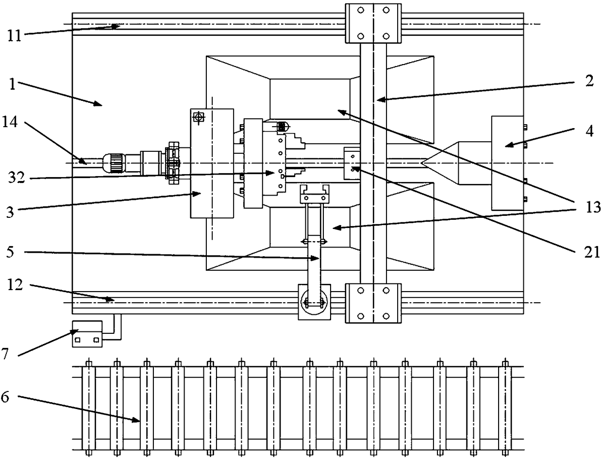
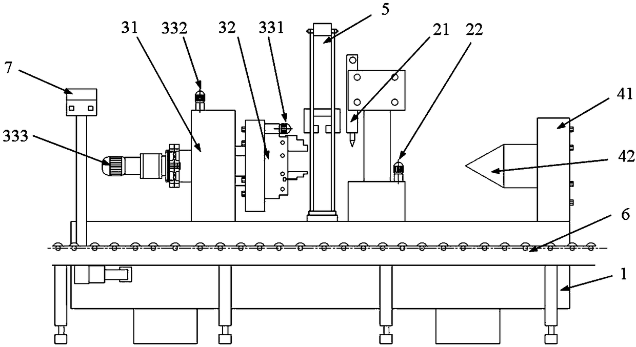
[0042] Generally speaking, for the bed 1 of the machine tool, the end with the headstock box is the front end, and the opposite end is the tail end, as shown in the figure, the end with the tailstock 4 is the tail end, and the clamp assembly One end of 3 is the head end. Although the clamp assembly 3 shown in the figure is a movable part, it does not affect the understanding of the head and tail of the bed 1.

[0043] In addition, generally relative to the head and tail, for example, on a common lathe, the side where the operator is located is the front side, and the side opposite to the front side is the rear side. In the figure, the side where the feeding roller table 6 is located is the front side, and the side where the linear guide rail 11 is located is the rear side.

[0044] see figure 1 and 2 A laser processing machine tool for automatic loading and unloading of round tube workpieces shown in , its basic structure includes three guide rails, of which the linear guide...


PUM


Abstract

The invention discloses a circular pipe workpiece automatic loading and unloading laser machine. The circular pipe workpiece automatic loading and unloading laser machine comprises a machine body, a cross beam spun on two linear guide rails, a laser head module, a three-jaw chuck, a first motor mounted at a driving end of a three-jaw chuck loosing and clamping mechanism for driving loosing and clamping of the three-jaw chuck, a second motor mounted on a fixture base for driving the fixture base to operate on a secondary guide rail, a third motor arranged at a driving end of a three-jaw chuck shaft on the fixture base for driving rotation of the three-jaw chuck, a feeding mechanism positioned on one side of the machine body and with a feeding direction parallel to a machine body guide rail, and a loading and unloading manipulator mounted on the side of the feeding mechanism on the machine body. The circular pipe workpiece automatic loading and unloading laser machine is suitable for circular pipe workpiece laser processing, is reasonable in structure, and is higher in automation degree.

Description

technical field [0001] The invention relates to a machine tool for laser processing of circular pipe workpieces. Background technique [0002] With the rapid development of the global industry, high requirements are placed on the production efficiency of the processing industry. Traditional laser processing machine tools use manual loading, which not only has high labor intensity for workers, but also low production efficiency, resulting in a large waste of resources. In addition, most of the existing laser processing machine tools are for processing flat workpieces, while there are few laser processing machine tools for round tube workpieces. [0003] Chinese patent document CN105269157A discloses a semi-automatic laser cutting machine, which is provided with a pair of chucks at the front and back of the machine tool for clamping pipes, and a number of support plates are provided at the same time, so that when only one chuck clamps the pipes, the The plate provides auxili...

Claims


Application Information

Patent Timeline
Patent Type & Authority Patents(China)
IPC IPC(8): B23K26/38B23K26/70
CPCB23K26/38B23K26/702
Inventor 李峰西王守仁索海生
Owner SHANDONG LEIMING CNC LASER EQUIP CO LTD
Why Eureka
Try Eureka