
Staged flow-adjustable turbine shell

A stage-type, turbine shell technology, applied in the direction of engine components, machines/engines, internal combustion piston engines, etc., can solve the problems that the casting process is difficult to meet the requirements, the exhaust gas utilization rate is not ideal, and the casting requirements of the intermediate wall are high, so as to achieve good matching, The effect of reducing imbalance and efficient matching

Active Publication Date: 2012-07-04
康跃科技(山东)有限公司
View PDF14 Cites 21 Cited by
  • Summary
  • Abstract
  • Description
  • Claims
  • Application Information

AI Technical Summary

Problems solved by technology

However, many of the dual runners of the current double runner turbine housing are arranged side by side, that is, the arc lengths of the two runners are equal, such as patent 201010279953.8, so that when the exhaust gas flows in the runners, the contact area with the runner wall is large, and the flow loss is large.
In addition, most of the currently known dual-channel turbine casings have only two working modes, namely, low-speed working conditions and high-speed working conditions, such as patent 201010279953.8 and patent 201010280157.6, which makes the exhaust gas utilization rate unsatisfactory in some medium-speed working conditions
Finally, the known double-channel turbine casing structure, especially the intermediate wall, has high casting requirements, and the existing casting process is not easy to meet the requirements

Method used


Image

  • Staged flow-adjustable turbine shell
  • Staged flow-adjustable turbine shell
  • Staged flow-adjustable turbine shell

Examples


Embodiment Construction

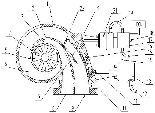
[0066] Examples such as figure 1 As shown, a stage-type adjustable flow turbine housing includes a turbine housing 1, a turbine assembly 4 and an exhaust gas inlet flow channel are installed in the turbine housing 1, and an intermediate wall 2 is provided in the exhaust gas intake flow channel. The intermediate wall 2. Divide the exhaust gas intake channel into an inner channel 3 and an outer channel 6. The turbine casing 1 is provided with an air inlet communicating with the exhaust gas inlet channel. The air inlet includes an inner channel communicating with the inner channel 3 The exhaust gas inlet 8 of the runner and the exhaust gas inlet 9 of the outer runner communicated with the outer runner 6 .

[0067] During installation, the exhaust gas inlet 8 of the inner runner and the exhaust gas inlet 9 of the outer runner are respectively connected to the exhaust pipe of the engine, and the other end of the turbine assembly 4 passes through the intermediate body and is connect...


PUM


Abstract

The invention discloses a staged flow-adjustable turbine shell, which comprises a turbine shell body. A turbine assembly and a waste gas inlet flow channel are mounted in the turbine shell body; an air inlet which is communicated with the waste gas inlet flow channel is arranged on the turbine shell body; an intermediate wall is disposed in the waste gas inlet flow channel and divides the waste gas inlet flow channel into an inner flow channel and an outer flow channel; a first valve device which can close the outer flow channel is disposed in the outer flow channel; and the intermediate wall is provided with a second valve device which can realize connection or disconnection of the inner flow channel and the outer flow channel. Waste gas energy is utilized sufficiently, rotation speed of a turbine rotor is increased, air inlet quantity of an engine in low speed work conditions is improved, so that the engine can apply more work, low speed torsion of the engine is increased, the low speed torque of the engine well matches with the low speed work conditions of the engine, and dynamic property and transient responsibility of the engine in low speed work conditions are improved.

Description

technical field [0001] The invention relates to a turbine casing, in particular to a stage-type adjustable flow turbine casing including a stage-type adjustable flow section, which can effectively meet the supercharging requirements of the engine under different working conditions, and belongs to the field of engine supercharging. Background technique [0002] With the society's increasing requirements on engine performance and emission, turbocharging technology is getting more and more attention. The supercharging technology increases the air intake pressure of the engine and increases the air intake density of the engine, so that the engine can enter more air in the same working volume, so it can correspondingly increase the fuel supply of the working cycle, so that the engine can do more work. The output power and torque of the engine are greatly improved, and the structure of the engine is relatively strengthened, so that the engine with the same power can adopt a smalle...

Claims


Application Information

Patent Timeline
Patent Type & Authority Applications(China)
IPC IPC(8): F02B37/16F02B25/24
CPCY02T10/146Y02T10/144F02B37/16F01D17/14F02B37/22F01D17/143Y02T10/12
Inventor 王航范厚传李永泰
Owner 康跃科技(山东)有限公司
Learn More