
Electrohydrodynamics printing device for cambered substrate and control method of electrohydrodynamics printing device for cambered substrate

A printing equipment and dynamics technology, applied in printing devices, printing, typewriters, etc., can solve problems affecting the precise formation of electrohydrodynamic printing patterns, the precise formation of curved substrates, and the morphology of functional devices

Active Publication Date: 2016-12-07
JIAXING UNIV
View PDF8 Cites 20 Cited by
  • Summary
  • Abstract
  • Description
  • Claims
  • Application Information

AI Technical Summary

Problems solved by technology

[0004] The electrohydrodynamic printing process is easily affected by parameters such as the moving speed of the moving platform, the applied voltage, and the spray height, which affect the precise formation of the electrohydrodynamic printing pattern, affect the morphology of functional devices, and thus affect their performance.
At present, the electrohydrodynamic printing equipment can only realize the mobile printing of the X, Y and Z axes, which is only suitable for the printing of flat substrates. For the electrohydrodynamic printing of curved substrates, due to the complex shape of curved substrates, only It is difficult to accurately control the jet height and the normal direction of the printing position through the movement of the Z axis, which affects the precise shape of the electrohydrodynamic printing thickness and pattern on the curved substrate

Method used


Image

  • Electrohydrodynamics printing device for cambered substrate and control method of electrohydrodynamics printing device for cambered substrate
  • Electrohydrodynamics printing device for cambered substrate and control method of electrohydrodynamics printing device for cambered substrate
  • Electrohydrodynamics printing device for cambered substrate and control method of electrohydrodynamics printing device for cambered substrate

Examples


Embodiment Construction

[0065] Embodiments of the present invention will be further described below with reference to the accompanying drawings:

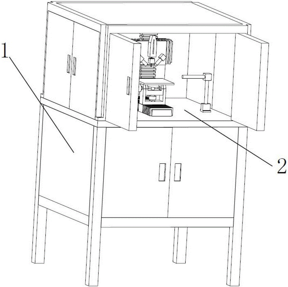
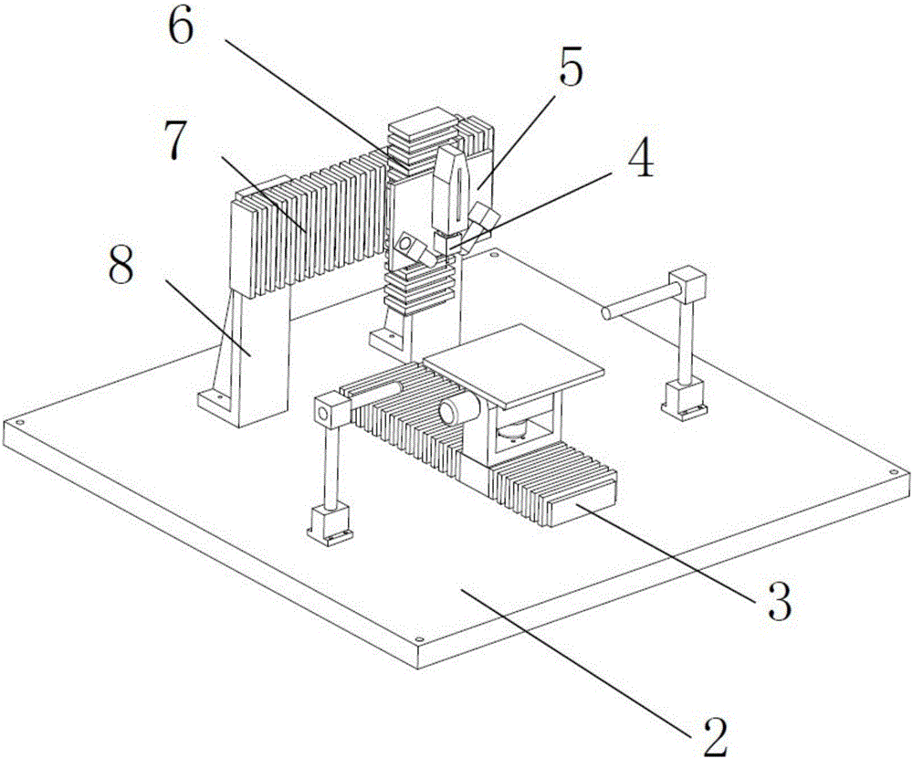
[0066] As shown in the figure, the present invention discloses an electrohydrodynamic printing device for a curved substrate, which includes a frame 1 on which a carrying platform 2 is arranged;

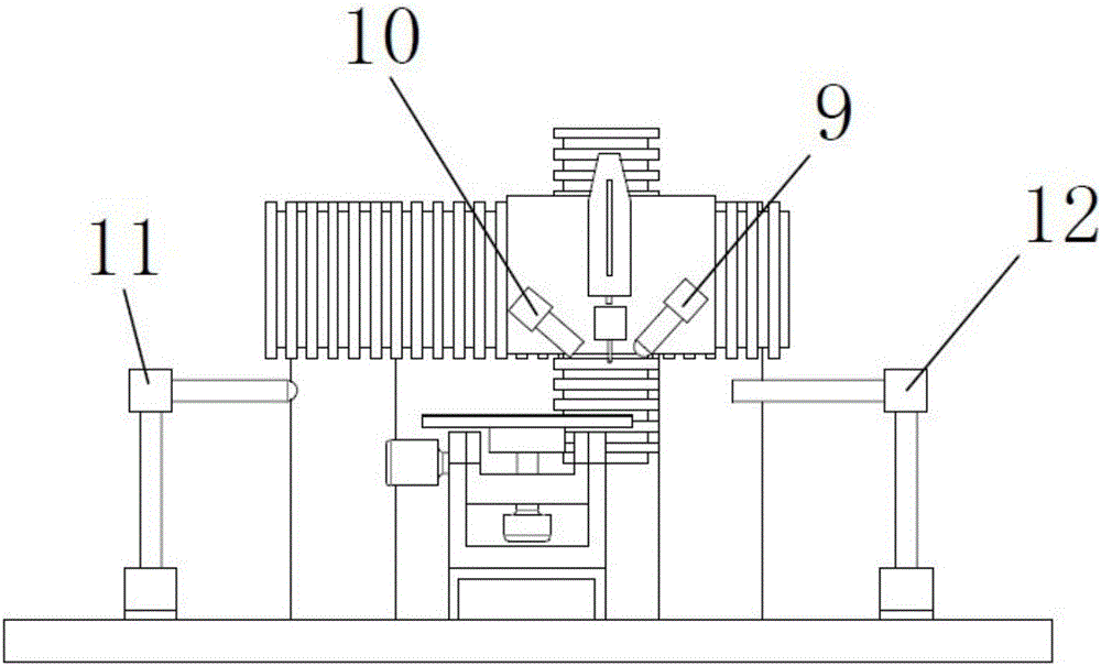
[0067] The printing module is erected on the carrying platform 2, and the X-axis and Z-axis sliding mechanisms of the printing module are arranged on the carrying platform, and it is provided with nozzles 4 for inkjet, which are used for inkjet onto the curved substrate to To print the pattern;

[0068] The printing module includes an inkjet mechanism, an X-axis sliding mechanism 7 and a Z-axis sliding mechanism 6. The X-axis sliding mechanism is arranged on a support frame 8, and the Z-axis sliding mechanism is arranged on the X-axis sliding mechanism. mechanism and forms an X-axis sliding cooperation with the X-phase sliding mechanism, and the inkjet mechanism...


PUM


Abstract

The invention discloses an electrohydrodynamics printing device for a cambered substrate and a control method of the electrohydrodynamics printing device for the cambered substrate. The electrohydrodynamics printing device comprises a machine frame, a printing module, a printing platform and a high voltage power supply module. The printing module can move horizontally along the X axis and the Z axis correspondingly, and the printing platform is provided with a printing surface and a Y-axis slipping mechanism; and the printing surface is arranged on the Y-axis slipping mechanism to move horizontally in the Y-axis direction, and simultaneously, the printing surface rotates circumferentially along the X axis and the Z axis correspondingly, so that the printing surface rotates around the A axis and the Z axis. According to the control method of the electrohydrodynamics printing device for the cambered substrate, the printing surface is driven to move horizontally along the X axis, the Y axis and the Z axis and rotate around the A axis and C axis correspondingly, so that spatial compound motion of the printing platform is achieved, and the electrohydrodynamics printing device can print electrohydrodynamics patterns on the cambered substrate.

Description

technical field [0001] The invention relates to the technical field of electrohydrodynamic printing, in particular to an electrohydrodynamic printing device for a curved substrate and a control method thereof. Background technique [0002] Electrohydrodynamic printing technology is to apply a voltage between the substrate and the nozzle. Under the action of the induced electric field force, the solution flows out of the nozzle and forms a meniscus at the nozzle. As the voltage gradually increases, the charge accumulates on the meniscus. The Coulomb force between the charges causes tangential stress on the surface of the liquid. Under the action of the shear force, the meniscus forms a Taylor cone at the top of the nozzle. As the electric field increases, the Coulomb force overcomes the surface tension of the liquid, and the liquid flows from the top of the Taylor cone. Shot, forming a droplet or jet. Electrohydrodynamic printing technology has received extensive attention i...

Claims


Application Information

Patent Timeline
IPC IPC(8): B41J3/407B41J29/393
CPCB41J3/4073B41J29/393B41J2029/3935
Inventor 张礼兵戴姚波吴婷黄风立左春柽李玉文郭燕郑丽君杨雪
Owner JIAXING UNIV
Learn More