Ship stabilizer

An anti-rolling device and technology for ships, applied in the field of ships, can solve the problems of complex and expensive fin anti-rolling devices, and achieve the effects of being easy to popularize and use, low in cost, and enhancing the ability to maintain level energy.

Active Publication Date: 2016-12-07
重庆渝赞企业管理咨询中心
View PDF13 Cites 0 Cited by
  • Summary
  • Abstract
  • Description
  • Claims
  • Application Information

AI Technical Summary

Problems solved by technology

However, at present, only anti-rolling tanks, bilge keels, and anti-rolling fins are widely used in the world. Among them, the anti-rolling fins installed on the bilges on b

Method used


Image

  • Ship stabilizer

Examples


Embodiment Construction

[0014] The following will clearly and completely describe the technical solutions in the embodiments of the present invention with reference to the accompanying drawings in the embodiments of the present invention. Obviously, the described embodiments are only some, not all, embodiments of the present invention. Based on the embodiments of the present invention, all other embodiments obtained by persons of ordinary skill in the art without making creative efforts belong to the protection scope of the present invention.

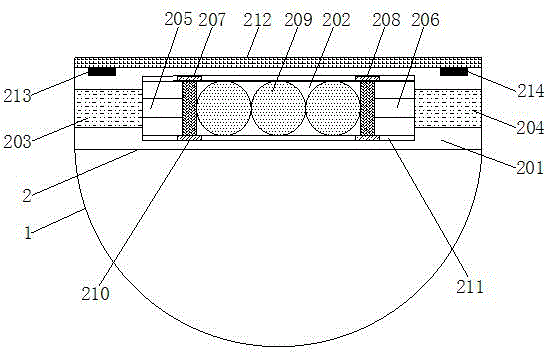
[0015] see figure 1 , the present invention provides a technical solution: a ship anti-rolling device, including a ship body 1, and the ship body 1 is provided with an anti-rolling device 2, and the anti-rolling device 2 includes a shell 201, and a cavity 202 is left inside the shell 201 , the shell walls on both sides of the cavity 202 are respectively provided with a first electro-hydraulic cylinder 203 and a second electro-hydraulic cylinder 204, and the fi...


PUM


Abstract

The invention discloses a ship stabilizer. The ship stabilizer comprises a ship body, wherein the ship body is provided with a stabilizer; the stabilizer comprises a shell; a cavity is maintained inside the shell; a first electric hydraulic cylinder and a second electric hydraulic cylinder are arranged in shell walls on two sides of the cavity respectively; the cavity is internally provided with a first hydraulic telescopic rod and a second hydraulic telescopic rod corresponding to the first electric hydraulic cylinder and the second electric hydraulic cylinder respectively; one end of the first hydraulic telescopic rod is connected with the first electric hydraulic cylinder, and the other end of the first hydraulic telescopic rod is fixedly connected with a first baffle plate; one end of the second hydraulic telescopic rod is connected with the second electric hydraulic cylinder, and the other end of the second hydraulic telescopic rod is fixedly connected with a second baffle plate. The ship stabilizer plays a good stabilization role when a ship shakes, so that the stabilizing capability of the ship is strengthened, and the device is simple in structure, relatively low in cost and convenient for popularization and application.

Description


Claims


Application Information

Patent Timeline
Owner 重庆渝赞企业管理咨询中心
Why Eureka
Try Eureka