Robot multi-camera visual inertia point-line feature positioning method and device

A multi-camera vision and feature localization technology, applied in manipulators, program-controlled manipulators, manufacturing tools, etc., can solve the problems of difficult repeated detection of feature points and false matching rate of feature points.

Active Publication Date: 2020-10-20
ZHEJIANG UNIV
View PDF5 Cites 10 Cited by
  • Summary
  • Abstract
  • Description
  • Claims
  • Application Information

AI Technical Summary

Problems solved by technology

[0004] The traditional visual positioning method based on feature point matching for camera fundamental matrix estimation is easily affected by problems such as viewing angle changes, ...

Method used


Image

  • Robot multi-camera visual inertia point-line feature positioning method and device
  • Robot multi-camera visual inertia point-line feature positioning method and device
  • Robot multi-camera visual inertia point-line feature positioning method and device

Examples


Embodiment Construction

[0070] In the following, the technical solutions of the present invention will be further described in conjunction with the drawings and specific implementation methods.

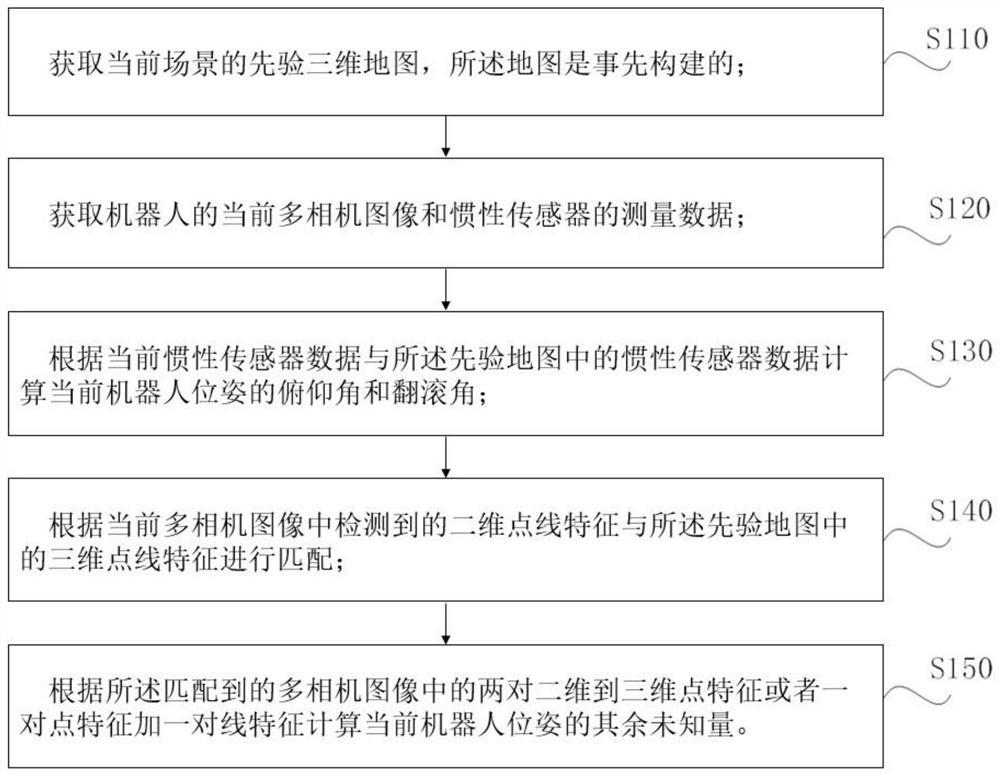
[0071] figure 1 It is a schematic flow chart of the robot visual inertial point and line feature positioning method of the present invention. The present invention discloses a robot visual inertia point line feature positioning method, which includes the following steps:

[0072] 1. Obtain a priori three-dimensional map of the current scene, the map is constructed in advance, and the map is required to include the measurement data of the acceleration of gravity in the map coordinate system, which is generally measured by an inertial sensor, specifically when determining the map coordinate system At the same time, the acceleration data measured by the inertial sensor is saved; the three-dimensional map also includes three-dimensional point-line features, so that it can be matched with the two-dimensional poin...


PUM


Abstract

The invention discloses a robot multi-camera visual inertia point-line feature positioning method and device. The method comprises the steps of obtaining a priori three-dimensional map of a current scene, and enabling the map to be constructed in advance; acquiring a current image of a robot and measurement data of an inertial sensor; matching the two-dimensional point and line features detected in the current image with the three-dimensional point and line features in the prior three-dimensional map; and calculating the yaw angle and translation of the current robot pose according to the twopairs of matched two-dimensional to three-dimensional point features or one pair of point features plus one pair of line features. At present, the main application fields of mobile robots are warehouse logistics, inspection monitoring and the like, and the requirements of the mobile robots on the robots are that the mobile robots can stably operate for a long time in a relatively fixed environmentand can realize accurate self-positioning. A visual sensor is low in production cost and large in acquired information amount, and related positioning methods are widely researched and applied.

Description

technical field [0001] The invention relates to robot positioning technology, in particular to a robot multi-camera visual inertia point line feature positioning method and device. Background technique [0002] With the development of mobile robot technology, mobile robots perform more and more types of tasks, and the connection with human life is getting closer. At present, the application scope of mobile robots includes logistics handling, express delivery, cleaning, inspection and unmanned driving, etc., which has greatly promoted the transformation and unmanned process of these industries. Achieving high-precision and long-term stable self-localization is a prerequisite for autonomous mobile robots to complete tasks. [0003] Although the visual positioning technology is less mature than the distance sensor, the camera is an indispensable sensor unit to provide intuitive environmental information for human-computer interaction; the cost of the camera is very low, and th...

Claims


Application Information

Patent Timeline
IPC IPC(8): B25J9/16
CPCB25J9/1661B25J9/1697
Inventor 王越焦艳梅熊蓉
Owner ZHEJIANG UNIV
Why Eureka
Try Eureka