Boost power conversion circuit and control method

A technology for converting circuits and power, which is applied in the field of step-up power conversion circuits and control, and can solve problems such as overvoltage breakdown and semiconductor overvoltage breakdown, so as to avoid overvoltage breakdown, reduce output waveform distortion, and improve system efficiency Effect

Active Publication Date: 2019-05-07
HUAWEI TECH CO LTD
View PDF7 Cites 0 Cited by
  • Summary
  • Abstract
  • Description
  • Claims
  • Application Information

AI Technical Summary

Problems solved by technology

[0004] However, according to the above analysis, it can be seen that Vout>Vin, all switching tubes can choose a withstand voltage of 0.5Vout; if there is no voltage on the flying capacitor, that is, Vc=0, and the capacitor voltage is 0, then the capacitor can be regarded as a short circuit, that is, the T1 tube Short-circuited by D1 and D5 in both directions, at this time T2 and D2 bear the input voltage Vin, and D6 bears the withstand voltage Vout-Vin; if Vin0.5Vout, if the withstand voltage exceeds D6, D6 will break down overvoltage; if Vin>0.5Vout, then T2 and D2 withstand the input voltage Vin, Vin>0.5Vout, if the withstand voltage of D2 and T2 exceeds 0.5Vout, D2 and T2 will break down due to overvoltage; D6 withstands the withstand voltage Vout-Vin, Vout-Vin<0.5Vout, not exceeding D6 Withstand voltage, D6 will not be overvoltage breakdown; from the above analysis, if the flying capacitor voltage Vc is zero, the semiconductors in the above scheme are at risk of overvoltage breakdown

Method used


Image

  • Boost power conversion circuit and control method
  • Boost power conversion circuit and control method
  • Boost power conversion circuit and control method

Examples


Embodiment Construction

[0041] In order to make the purpose, technical solutions and advantages of the embodiments of the present invention clearer, the technical solutions in the embodiments of the present invention will be clearly and completely described below in conjunction with the drawings in the embodiments of the present invention. Obviously, the described embodiments It is a part of embodiments of the present invention, but not all embodiments. Based on the embodiments of the present invention, all other embodiments obtained by persons of ordinary skill in the art without making creative efforts belong to the protection scope of the present invention.

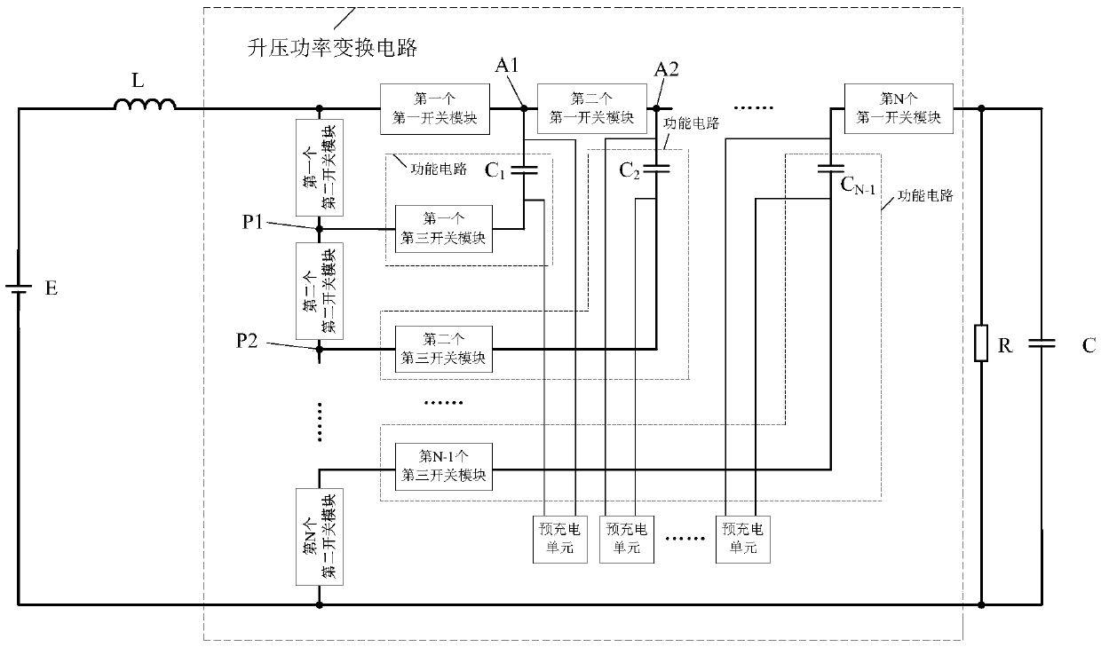
[0042] figure 2 The principle diagram of the first embodiment of the step-up power conversion circuit provided by the present invention, such as figure 2 As shown, the boost power conversion circuit provided by the present invention includes: N first switch modules, N second switch modules, N-1 third switch modules, N-1 flying capacitors (...


PUM


Abstract

A boost power conversion circuit and a control method. The circuit comprises: N first switch modules, N second switch modules, N-1 third switch modules, N-1 flying capacitors, and N-1 pre-charging units. The N second switch modules are connected in series to an inductor and to an input power supply to form a loop. The N first switch modules are connected in series to a load, to the inductor, and to the input power supply to form a loop. A flying capacitor and a third switch module are connected between a first common point between the first switch modules and a second common point between the second switch modules. Each flying capacitor is connected in parallel to a pre-charging unit. Each pre-charging unit is used for pre-charging, when a third switch module that is connected to the flying capacitor connected in parallel to the pre-charging unit is switched off and the voltage of the flying capacitor is less than a preset threshold, the flying capacitor. The boost power conversion circuit and the control method can ensure that the voltage of the flying capacitors does not drop to 0 V, thereby avoiding the problem of possible breakdown in a semiconductor device due to overvoltage when a boost power conversion circuit is used in a high voltage system.

Description

technical field [0001] Embodiments of the present invention relate to electronic circuit technologies, and in particular, to a boost power conversion circuit and a control method. Background technique [0002] Boost circuit does not specifically refer to a specific circuit, but generally refers to a boost circuit, that is, through the circuit to input a voltage, output a higher voltage, realize power conversion, and can input greater than or equal to three levels called It is a multi-level Boost circuit. [0003] Figure 1a It is a flying capacitor multi-level boost circuit, Figure 1b It is a schematic diagram of the control signal of a flying capacitor multi-level Boost circuit, such as Figure 1a , Figure 1b As shown, L is an inductor, D1, D2, D5, D6 are diodes, T1, T2 are semiconductor switches (can be insulated gate bipolar transistors (English: Insulated Gate Bipolar Transistor, referred to as: IGBT), metal-oxide layer Semiconductor field effect transistor (English...

Claims


Application Information

Patent Timeline
Patent Type & Authority Patents(China)
IPC IPC(8): H02M3/155
CPCH02M3/155
Inventor 叶飞石磊刘云峰
Owner HUAWEI TECH CO LTD
Why Eureka
Try Eureka