Mechanical changer for changing end effectors

A mechanical and damper technology, which is applied in the field of mechanical replacement devices, can solve problems such as unsatisfactory bonding strength, hazards to replacement device staff, and inconvenient operation

Active Publication Date: 2018-11-06
HIWIN TECH
View PDF9 Cites 0 Cited by
  • Summary
  • Abstract
  • Description
  • Claims
  • Application Information

AI Technical Summary

Problems solved by technology

[0003] As far as the prior art of the replacement device is concerned, at first such as U.S. Patent No. 6,073,512 is to manually operate the handle so that the handle drives the sprocket to rotate. In addition to the problem of inconvenient operation, if the latch accidentally falls off during operation, the replacement device that loses the locking ability can easily cause harm to the staff
Another example is U.S. Patent No. 4,708,548, which controls the action of the positioning ball by manually rotating the inner cam ring. When the positioning ball is embedded in the groove, the first and second units are joined together. When the positioning ball When breaking away from the groove, the first and second units can be separated, but in this existing patent, the bonding strength between the first and second units is not ideal, so it will limit the end effectors that cooperate with it weight and specifications
Finally, for example, U.S. Patent No. 2007 / 0235949 uses pressurized fluid to push the piston, so that the piston is pushing the steel ball to complete the engagement between the first and second units. When the first and second units are to be separated, it is in reverse Input the pressurized fluid to the pressurized fluid to push the piston away from the steel ball. At this time, the steel ball can be separated by itself. However, it can be found from the existing patent case that in order to use the pressurized fluid, it is necessary to add an additional structure. Equipment (such as pipelines, air tanks or booster pumps), but this will not only lead to an increase in cost, but also cause inconvenience in movement because the entire machine is too large

Method used


Image

  • Mechanical changer for changing end effectors
  • Mechanical changer for changing end effectors
  • Mechanical changer for changing end effectors

Examples


Embodiment Construction

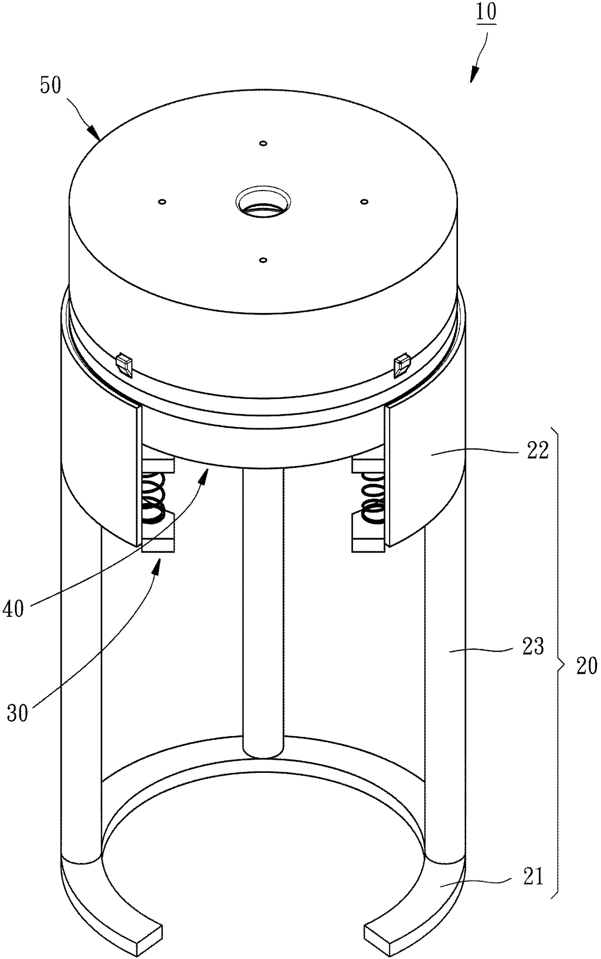
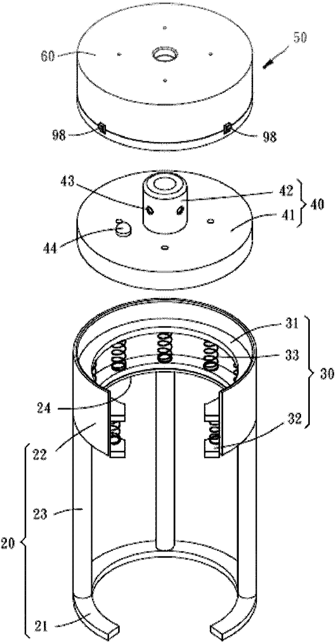
[0045] see figure 1 and figure 2 , the mechanical replacement device 10 of the first embodiment of the present invention includes a base 20 , a damper 30 , a first connection unit 40 , and a second connection unit 50 .

[0046] The base 20 has a bottom wall 21, a ring wall 22 above the bottom wall 21, and three support rods 23 connected between the bottom wall 21 and the ring wall 22, wherein the inner ring surface of the ring wall 22 has an inner flange24.

[0047] The damper 30 can choose to use a viscoelastic damper, a hydraulic damper or a vibration damper. In this embodiment, a viscoelastic damper 30 (Viscoelastic damper) is the best implementation, but not limited thereto. The damper 30 has an upper support plate 31 , a lower support plate 32 , and a plurality of viscoelastic damping elements 33 connected between the upper and lower support plates 31 , 32 . When assembled, the damper 30 is placed on the inner flange 24 of the ring wall 22 of the base 20 through the l...


PUM


Abstract

The invention relates to a mechanical replacement device used for replacing an end effector. The mechanical replacement device used for replacing the end effector mainly comprises a first connecting unit and a second connecting unit, wherein a plurality of movable pieces and a plurality of elastic pieces are arranged in the second connecting unit, and each movable piece is matched with one elastic piece; and in this way, through the linkage relation between the movable pieces and the elastic pieces, the first connecting unit and the second connecting unit can be connected or separated automatically, and the function of replacing the end effector is achieved successfully.

Description

technical field [0001] The invention relates to a device for replacing an end effector used with a mechanical arm, in particular to a mechanical replacement device. Background technique [0002] Robotic arms have been widely used in the manufacturing and processing industry at present. On the one hand, it can reduce the reduction of product yield caused by manual execution of highly repetitive workflows. On the other hand, it can replace manual work in harsh environmental conditions. , so that the health of the staff can be avoided, and at the same time, good processing accuracy can be maintained. However, during the manufacturing process, the robot arm must be equipped with a replacement device to replace end effectors of different specifications (such as grippers, suction cups or drills), so as to process workpieces of different specifications. [0003] As far as the prior art of the replacement device is concerned, at first such as U.S. Patent No. 6,073,512 is to manuall...

Claims


Application Information

Patent Timeline
Patent Type & Authority Patents(China)
IPC IPC(8): B25J15/04
Inventor 翁振民吕明修黄彦舜
Owner HIWIN TECH
Why Eureka
Try Eureka