Anti-rollover device for railway long rail transportation

A long rail and anti-rollover technology, which is applied in transportation and packaging, railway car body parts, cargo support/securement parts, etc., can solve problems such as increased labor intensity, complicated maintenance and maintenance, and reduced work efficiency, so as to reduce loading and unloading and transport process procedures, improve transport work efficiency, and reduce the effect of personal safety accidents

Active Publication Date: 2018-03-30
TIANJIN LOCOMOTIVE CO LTD
View PDF6 Cites 0 Cited by
  • Summary
  • Abstract
  • Description
  • Claims
  • Application Information

AI Technical Summary

Problems solved by technology

[0002] The long rails of the railway need to be loaded and unloaded during the transportation process. Due to their long length and poor rigidity, during the loading and unloading process of the rails, the rails are prone to rollover when pulling the rails.
At present, the rail is loaded and unloaded at home and abroad by pulling the rail from one end and loading and unloading it to the designated position. The anti-rollover device of the rail is mainly clamped by a hydraulic device. However, the existing anti-rollover device for the rail is cumbersome and cumbersome, and the hydraulic oil is easy to leak , overhaul and maintenance are complex, and rail loading and unloading and transportation processes require personnel to operate, frequent operations, waste of man-hours, increased labor intensity, and reduced work efficiency

Method used


Image

  • Anti-rollover device for railway long rail transportation
  • Anti-rollover device for railway long rail transportation
  • Anti-rollover device for railway long rail transportation

Examples


Embodiment Construction

[0024] The present invention will be further described below in conjunction with the accompanying drawings.

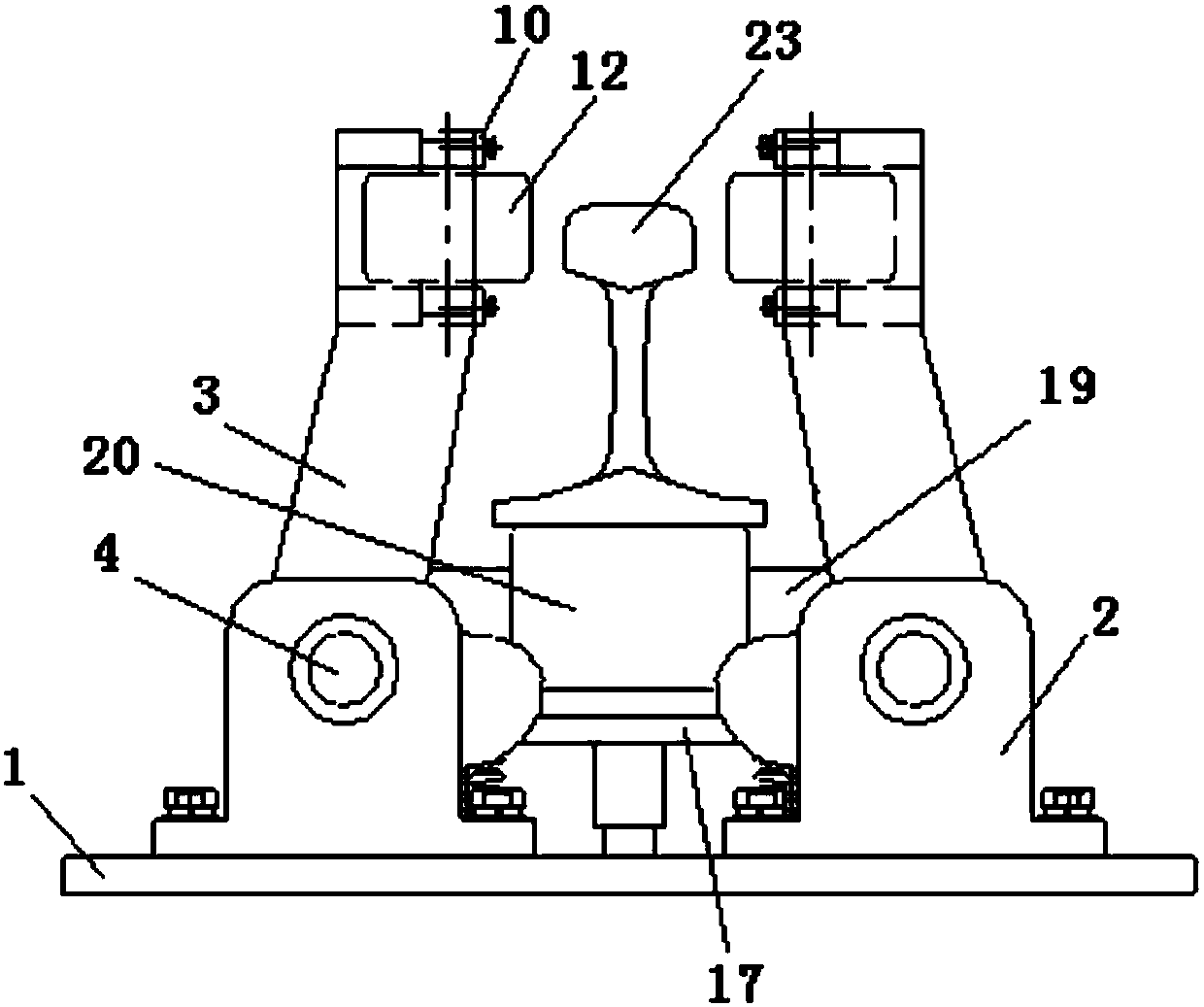
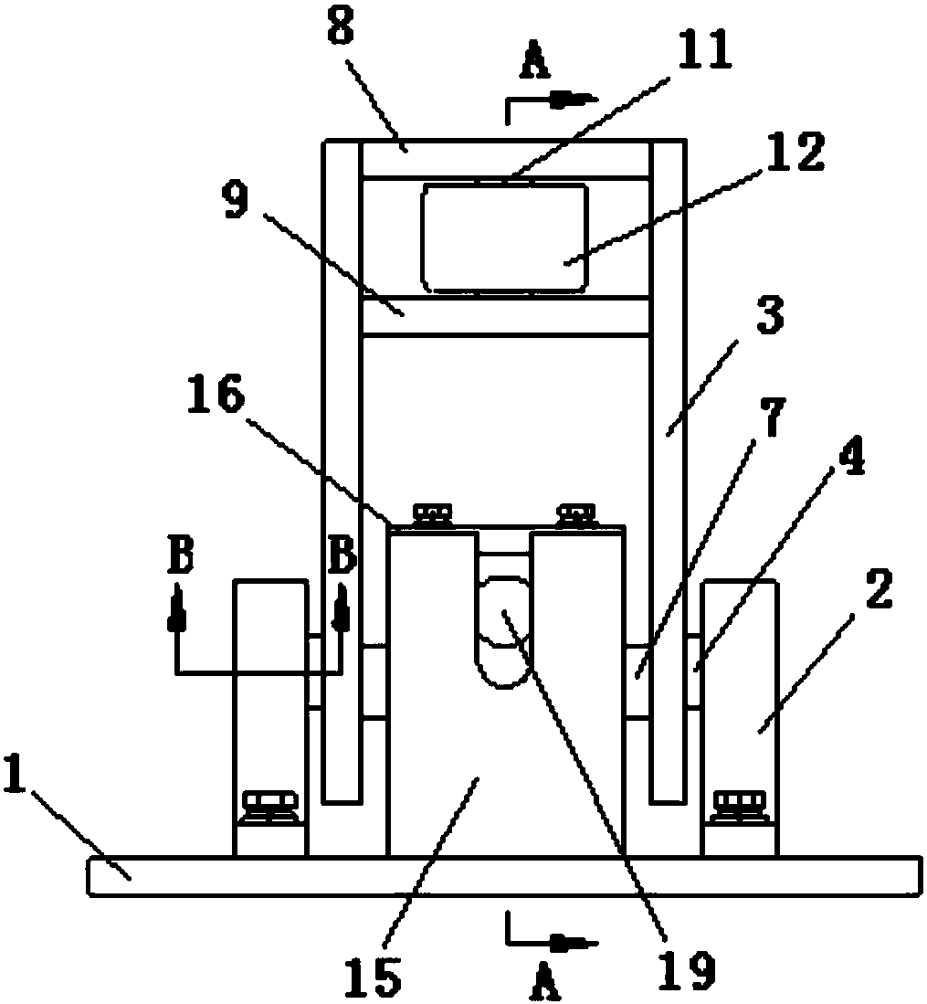
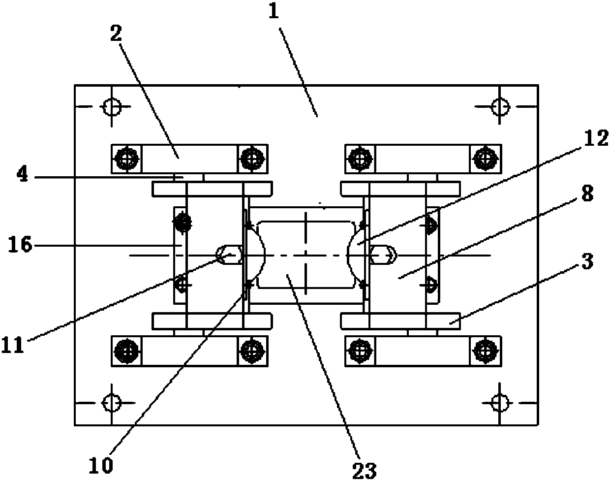
[0025] Such as Figure 1 to Figure 9 As shown, a long railway rail transportation anti-rollover device of the present invention includes a fixed seat 1 fixed on the car body by bolts, and two pairs of bearing seats 2 are arranged in parallel on the fixed seat 1, which are arranged in two rows and two Columns, bolted on. Two foot-shaped plates 3 are arranged between each pair of bearing blocks 2, and a rotating shaft 4 integrally formed with the foot-shaped plate 3 is arranged on the outer side thereof, and the rotating shaft 4 is rotationally connected with the bearing blocks 2, and the bearing The seat 2 is provided with a bearing hole for installing the rotating shaft 4, and the first retaining ring 6 and the rotating bearing 5 sleeved on the rotating shaft 4 are arranged in the bearing hole. Can be rotated relatively. Every pair of said foot-shaped plates 3 is fi...


PUM


Abstract

The invention discloses a rollover prevention device for railway long steel rail transportation. The rollover prevention device comprises a fixed base, two pairs of bearing seats are arranged in parallel on the fixed base, two foot type plates are arranged between each pairs of the bearing seats, and a rotation axis is arranged on the outer side of each foot type plate, the rotation axis is in rotary connection with the corresponding bearing seat; each pair of foot type plates are fixedly connected through arranging a connection shaft at the lower end portions of the foot type plates, and a coverplate and a support plate are arranged in parallel on the upper end portions of each pair of foot type plates; a first rolling shaft which is arranged in a first roller in a sleeved mode is perpendicularly arranged between the coverplate and the support plate, a base side plate which is fixedly connected with the fixed base is perpendicularly arranged between each pair of the foot type plates, and a U-shaped groove is formed in each base side plate from top to down, a second rolling shaft which is located at the upper end of the connection shaft is arranged between the U-shaped grooves of the two base side plates, and the second rolling shaft is arranged on a second roller in a sleeved mode; a spring seat which is located at the lower end of the connection shaft is arranged between the two base side plates, a spring is arranged between the spring seat and the fixed base. According to the rollover prevention device for railway long steel rail transportation, safety and reliability of the rail transportation can be guaranteed, moreover, transportation efficiency can be ensured.

Description

technical field [0001] The invention relates to a railway machine tool, in particular to an anti-rollover device for railway long rail transportation. Background technique [0002] The long rails of the railway need to be loaded and unloaded during the transportation process. Due to their long length and poor rigidity, during the loading and unloading process of the rails, the rails are prone to rollover when pulling the rails. . At present, the rail is loaded and unloaded at home and abroad by pulling the rail from one end and loading and unloading it to the designated position. The anti-rollover device of the rail is mainly clamped by a hydraulic device. However, the existing anti-rollover device for the rail is cumbersome and cumbersome, and the hydraulic oil is easy to leak , Overhaul and maintenance are complex, rail loading and unloading and transportation processes require personnel to operate, frequent operations, waste of working hours, increased labor intensity, a...

Claims


Application Information

Patent Timeline
Patent Type & Authority Patents(China)
IPC IPC(8): B61D45/00
CPCB61D45/001
Inventor 廖道鹏王国政李娜王小燕辛志锋
Owner TIANJIN LOCOMOTIVE CO LTD
Why Eureka
Try Eureka