A low-speed cooling water heat protection device

A technology for cooling water and heat protection, which is applied in the direction of indirect heat exchangers, heat exchanger types, lighting and heating equipment, etc., which can solve the problems of large protection area, increased construction cost of test equipment, and long time of heat protection , to achieve the effect of reducing the pressure loss along the way

Active Publication Date: 2019-01-11
BEIJING AEROSPACE INST OF THE LONG MARCH VEHICLE +1
View PDF6 Cites 0 Cited by
  • Summary
  • Abstract
  • Description
  • Claims
  • Application Information

AI Technical Summary

Problems solved by technology

Such a method is difficult to efficiently solve the problem of high heat flow and long-term thermal protection of the diffuser
Specifically, there are two difficulties: First, the structural design is difficult. Due to the characteristics of high pressure and high flow rate of cooling water, high requirements are placed on the strength of the diffuser. Therefore, stainless steel with better strength is usually selected, but the thermal conductivity of stainless steel Smaller, about 1 / 3 of carbon steel, which requires the inner wall of the diffuser to be made very thin to reduce thermal resistance; second, the demand for cooling water is large, and the thermal protection time is long (above 1000s). The diffuser needs to protect a large area and the water flow rate is fast. These characteristics determine the large demand for cooling water and increase the construction cost of the test equipment.

Method used


Image

  • A low-speed cooling water heat protection device
  • A low-speed cooling water heat protection device

Examples


Embodiment Construction

[0019] Below in conjunction with accompanying drawing and specific embodiment the present invention is described in further detail:

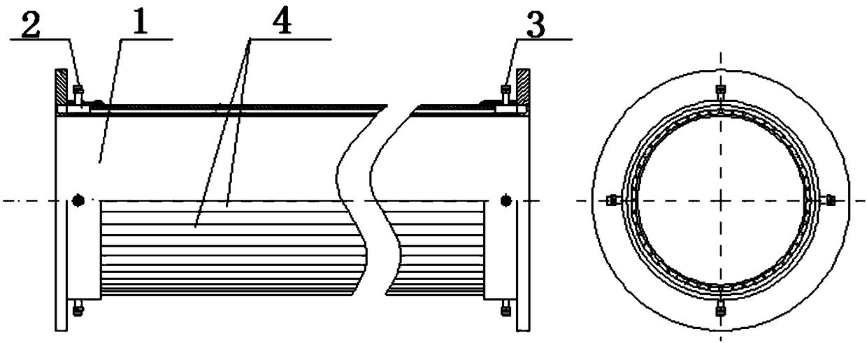
[0020] The invention adopts the design method of subcooling and boiling to realize the long-term thermal protection of the diffuser in the megawatt-level thermal environment at a relatively low flow rate and relatively low pressure, and ensure the normal operation of the high-temperature hot gas flow wind tunnel.

[0021] The structural composition of the diffuser long-term thermal protection method under the condition of megawatt-level heat flow includes a water collection chamber 1, a water inlet 2, a water outlet 3, and a water cooling channel 4; first, the required cooling water flow rate is calculated according to the actual heat flow conditions, and then Calculate the flow rate of water in the jacket of different sections of the diffuser, and then adjust the cooling water flow rate through the regulating valve to achieve the required flow r...


PUM


Abstract

The invention provides a low-speed cooling water thermal protection device and relates to the technical field of aircraft heat shielding ground testing. The low-speed cooling water thermal protection device comprises a water collecting cavity, a water inlet, a water outlet and water cooling channels. The water collecting cavity is of a hollow cylindrical structure. The water inlet is fixedly installed at one end of the outer wall of the water collecting cavity, and the water outlet is fixedly installed at the other end of the outer wall of the water collecting cavity. The multiple adjacent water cooling channels are arranged between the outer wall and the inner wall of the water collecting cavity in the axial direction of the water collecting cavity. Channel connection of cooling water of the water inlet and cooling water of the water outlet is achieved through the water cooling channels. By the adoption of the subcooled boiling design method, long-term thermal protection on a diffuser in the megawatt-grade thermal environment is achieved at the low flow rate and small pressure, and normal operation of a high-temperature hot gas flow wind tunnel is guaranteed; and long-term thermal protection on the diffuser in the high-temperature thermal structure wing tunnel is achieved, protection on the diffuser in the megawatt-grade thermal environment can be achieved at the low flow rate and small pressure, the difficulty of structural design is lowered, the requirement for cooling water amount is reduced, and normal operation of the gas flow wind tunnel is guaranteed.

Description

technical field [0001] The invention relates to the technical field of aircraft heat protection ground tests, in particular to a low-speed cooling water heat protection device. Background technique [0002] In the high-temperature gas flow wind tunnel, the diffuser is an important part, which is used to decelerate and pressurize the gas, diffuse the high-speed and low-pressure gas in the test chamber to the pressure condition required by the extraction system, and ensure the smooth discharge of the gas . The diffuser is composed of a converging section, a second throat, and an expanding section. The maximum heat flow of the converging section closest to the test piece is about 2MW / m2. Its long-term thermal protection is a major difficulty. There are two specific aspects: One is the high heat flux density, which requires the heat transfer form of thermal protection to have a higher heat transfer coefficient, and at the same time puts forward high requirements for the materia...

Claims


Application Information

Patent Timeline
Patent Type & Authority Patents(China)
IPC IPC(8): F28D7/16
CPCF28D7/1684
Inventor 田宁邹样辉齐斌曹知红岳晖张凯张利嵩那伟杨驰赵玲李彦良王镭夏吝时肖泽娟张昕曹宇清姜一通李文浩鲁宇朱广生李建林孟刚周岩水涌涛张岩陈卫国刘召军
Owner BEIJING AEROSPACE INST OF THE LONG MARCH VEHICLE
Why Eureka
Try Eureka