Stator assembly method and stator assembly device

一种组装方法、定子的技术,应用在机电装置、电动组件、预制绕组嵌入电机等方向,能够解决插入负载增大、线圈形状精度变差、线圈受伤等问题,达到抑制插入负载的效果

Active Publication Date: 2019-04-09
AISIN AW CO LTD
View PDF9 Cites 0 Cited by
  • Summary
  • Abstract
  • Description
  • Claims
  • Application Information

AI Technical Summary

Problems solved by technology

Therefore, when assembling to the stator core, after the assembly, the deformation of the coil part accommodated in the slot increases, and the pressure (surface pressure) of the coil pressed against the wall surface of the tooth in the slot increases, resulting in insertion The problem of increased load
As a result, problems such as damage to the coil, deterioration of the shape accuracy of the assembled coil, and enlargement of the equipment may occur.

Method used


Image

  • Stator assembly method and stator assembly device
  • Stator assembly method and stator assembly device
  • Stator assembly method and stator assembly device

Examples


Embodiment Construction

[0027] Hereinafter, specific embodiments of the stator assembly method and the stator assembly device of the present invention will be described using the drawings.

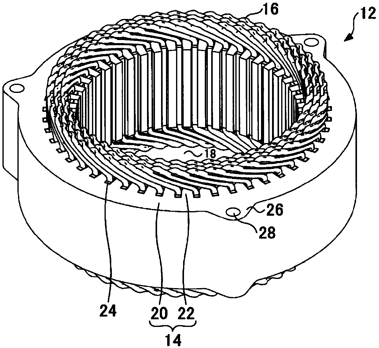
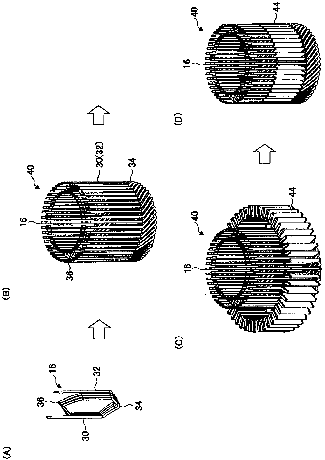
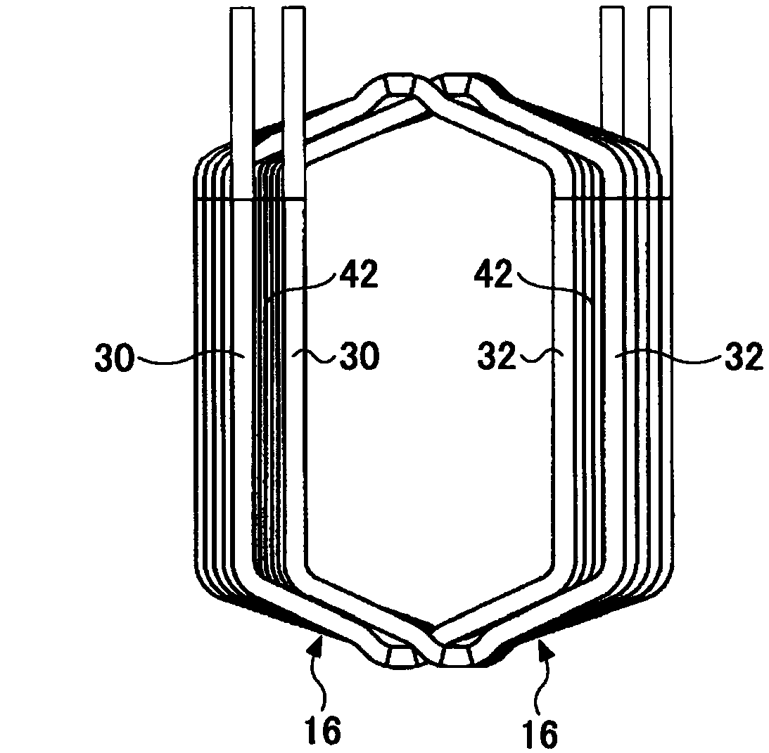
[0028] figure 1 It is a perspective view of a stator assembled using a stator assembling method and a stator assembling device according to an embodiment of the present invention. figure 2 It is a figure which shows the procedure which forms the coil assembly of the annular cage shape by several concentric windings in this Example. In addition, FIG. 3 is a diagram showing the positional relationship of two concentric windings of the same phase that accommodate the slot housing portion in the same slot in the present embodiment. In addition, FIG. 3(A) shows a view viewed from the shaft center side, and FIG. 3(B) shows a view viewed from the axial side.

[0029] The stator assembly device 10 of the present embodiment is a device for assembling the stator 12 which is a stator used in a rotating electric machine s...


PUM


Abstract

The invention provides a stator assembling method and a stator assembling device. The stator assembly method is to insert a coil assembly composed of a plurality of coils having a coil end and a linear portion from the inner diameter side toward the outer diameter side of an annular stator core, and install it on the stator core. To suppress the amount of coil deformation before each coil is inserted into the slot, the coil having the slot accommodation portion formed by the wire and the coil end is attached to the annular stator core having teeth and slots, and a plurality of coils are formed by forming A ring-shaped coil assembly is arranged, a guide jig is arranged on the coil assembly, and a plurality of coils are placed in a state where the coil assembly is arranged in the space on the inner diameter side of the stator core and the guide surface of the guide jig is parallel to the wall surface of the tooth. The plurality of coils are guided by the guide jig by radially pressing from the inner diameter side to the outer diameter side, and the slot receiving portions of the coils are inserted into the slots of the stator core.

Description

technical field [0001] The present invention relates to a stator assembling method and a stator assembling device, and particularly relates to installing a coil having a slot receiving portion formed of a wire and a coil end portion on a base having a plurality of teeth extending radially inward from a back yoke and formed on a Method and apparatus for an annular stator core with slots between two teeth. Background technique [0002] Conventionally, a stator assembling method and a stator assembling device for attaching a coil to an annular stator core are known (for example, refer to Patent Document 1). The stator core has a plurality of teeth extending radially inward from the back yoke, and slots formed between the two teeth. In addition, the coil is formed of a wire, and has a straight portion accommodated in the slot and a coil end located outside the slot. A ring-shaped coil assembly is formed by combining a plurality of coils. [0003] The stator assembly device de...

Claims


Application Information

Patent Timeline
Patent Type & Authority Patents(China)
IPC IPC(8): H02K15/085H02K15/06
CPCH02K15/066H02K15/06H02K15/085H02K1/146H02K15/026H02K15/062
Inventor 桥本伸吾前田秀户村真澄佐藤真吾
Owner AISIN AW CO LTD
Why Eureka
Try Eureka