Stator assembly method and stator assembly device

An assembly method and stator technology, which are used in electromechanical devices, electric components, and prefabricated windings embedded in motors, etc., can solve the problems of increased insertion load, coil injury, and poor coil shape accuracy, and achieve the effect of suppressing the insertion load.

Active Publication Date: 2017-02-15
AISIN AW CO LTD
View PDF9 Cites 11 Cited by
  • Summary
  • Abstract
  • Description
  • Claims
  • Application Information

AI Technical Summary

Problems solved by technology

Therefore, when assembling to the stator core, after the assembly, the deformation of the coil part accommodated in the slot increases, and the pressure (surface pressure) of the coil pressed against the wall surface of the tooth in the slot increases, resulting in insertion The problem of increased load
As a result, problems such as damage to the coil, deterioration of the shape accuracy of the assembled coil, and enlargement of the equipment may occur.

Method used


Image

  • Stator assembly method and stator assembly device
  • Stator assembly method and stator assembly device
  • Stator assembly method and stator assembly device

Examples


Embodiment Construction

[0027] Hereinafter, specific embodiments of the stator assembly method and the stator assembly device of the present invention will be described using the drawings.

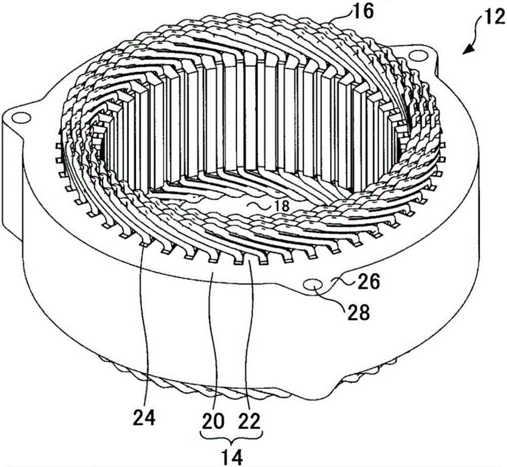
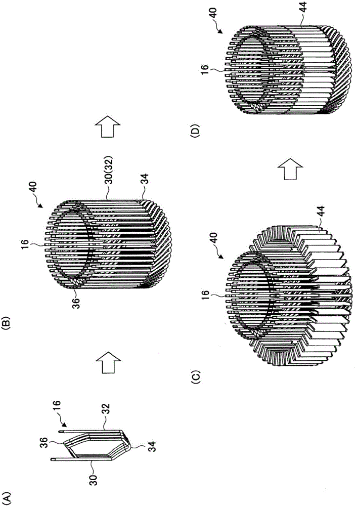
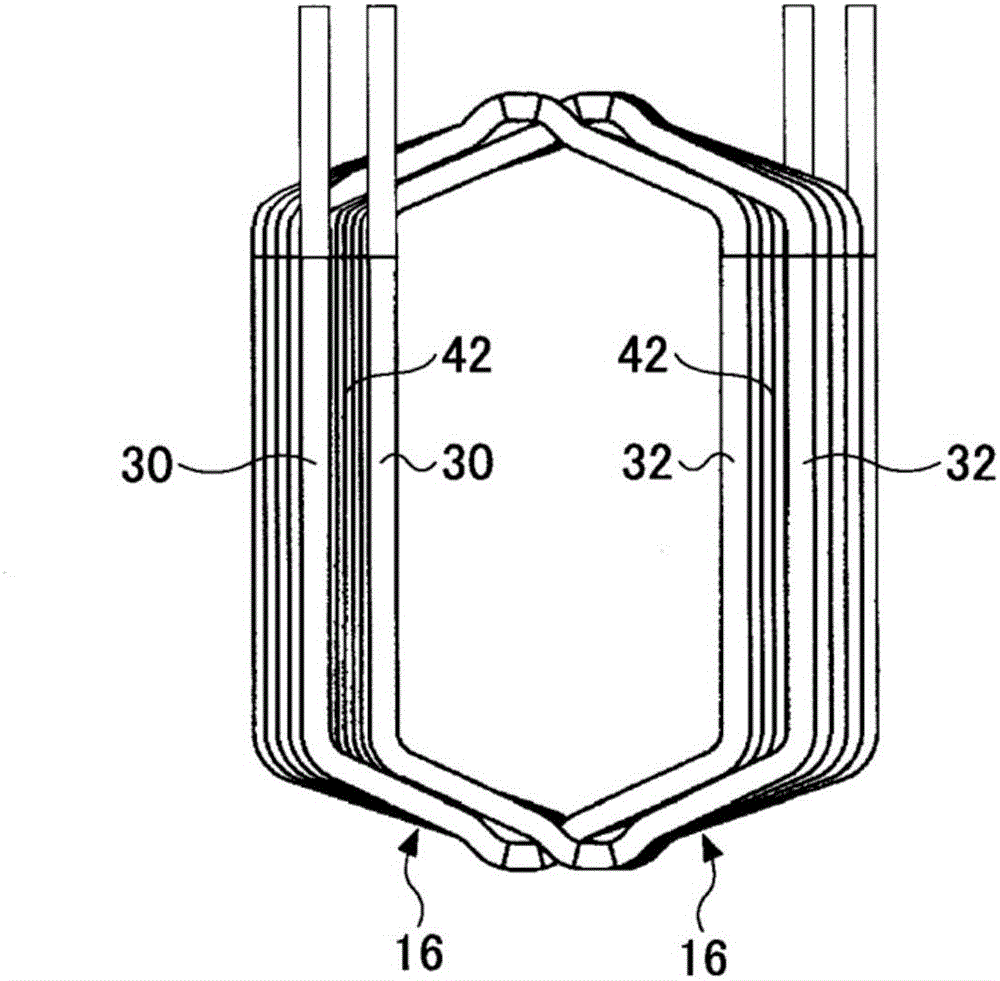
[0028] figure 1 It is a perspective view of a stator assembled using a stator assembling method and a stator assembling device according to an embodiment of the present invention. figure 2 It is a figure which shows the procedure which forms the coil assembly of the annular cage shape by several concentric windings in this Example. In addition, FIG. 3 is a diagram showing the positional relationship of two concentric windings of the same phase that accommodate the slot housing portion in the same slot in the present embodiment. In addition, FIG. 3(A) shows a view viewed from the shaft center side, and FIG. 3(B) shows a view viewed from the axial side.

[0029] The stator assembly device 10 of the present embodiment is a device for assembling the stator 12 which is a stator used in a rotating electric machine s...


PUM


Abstract

The purpose of the present invention is to suppress a coil deformation amount before inserting each coil into a slot when inserting a coil assembly from the inner diameter side toward outer diameter side of a circular ring-shaped stator core and thereby mounting the coil assembly on the stator core, said coil assembly being formed by combining a plurality of coils each having a coil end portion and a linear portion. A stator assembly method is a method for mounting a coil on a circular ring-shaped stator core having teeth and slots, said coil being formed of a conducting wire and having a slot-housed portion and a coil end portion. In the stator assembly method, a coil assembly is formed in which a plurality of coils are disposed in a circular ring shape, and a guide tool is disposed in the coil assembly. The coil assembly in which the guide tool is disposed is disposed in the inner diameter side space of the stator core and the coils are pushed out radially from the inner diameter side to the outer diameter side while maintaining a state in which the guide surface of the guide tool is parallel with a tooth wall surface, thereby inserting the slot-housed portions of the coils into the slots of the stator core while guiding the coils by the guide tool.

Description

technical field [0001] The present invention relates to a stator assembling method and a stator assembling device, and particularly relates to installing a coil having a slot receiving portion formed of a wire and a coil end portion on a base having a plurality of teeth extending radially inward from a back yoke and formed on a Method and apparatus for an annular stator core with slots between two teeth. Background technique [0002] Conventionally, a stator assembling method and a stator assembling device for attaching a coil to an annular stator core are known (for example, refer to Patent Document 1). The stator core has a plurality of teeth extending radially inward from the back yoke, and slots formed between the two teeth. In addition, the coil is formed of a wire, and has a straight portion accommodated in the slot and a coil end located outside the slot. A ring-shaped coil assembly is formed by combining a plurality of coils. [0003] The stator assembly device de...

Claims


Application Information

Patent Timeline
Patent Type & Authority Applications(China)
IPC IPC(8): H02K15/085H02K15/06
CPCH02K15/066H02K15/06H02K15/085H02K1/146H02K15/026H02K15/062
Inventor 桥本伸吾前田秀户村真澄佐藤真吾
Owner AISIN AW CO LTD
Why Eureka
Try Eureka