Vehicle Pneumatic Tires

A vehicle and tire technology, applied in the reinforcement layer of pneumatic tires, heavy-duty tires, heavy-duty vehicles, etc., can solve the problems of residual mobility, affecting durability and wear, and achieve improved durability, increased durability, and good wear and tear. and long-term structural durability

Active Publication Date: 2018-08-10
CONTINENTAL REIFEN DEUTSCHLAND GMBH
View PDF7 Cites 0 Cited by
  • Summary
  • Abstract
  • Description
  • Claims
  • Application Information

AI Technical Summary

Problems solved by technology

However, the formed inner working layer has residual mobility
This still may also unintentionally adversely affect durability and wear

Method used


Image

  • Vehicle Pneumatic Tires
  • Vehicle Pneumatic Tires
  • Vehicle Pneumatic Tires

Examples


Embodiment Construction

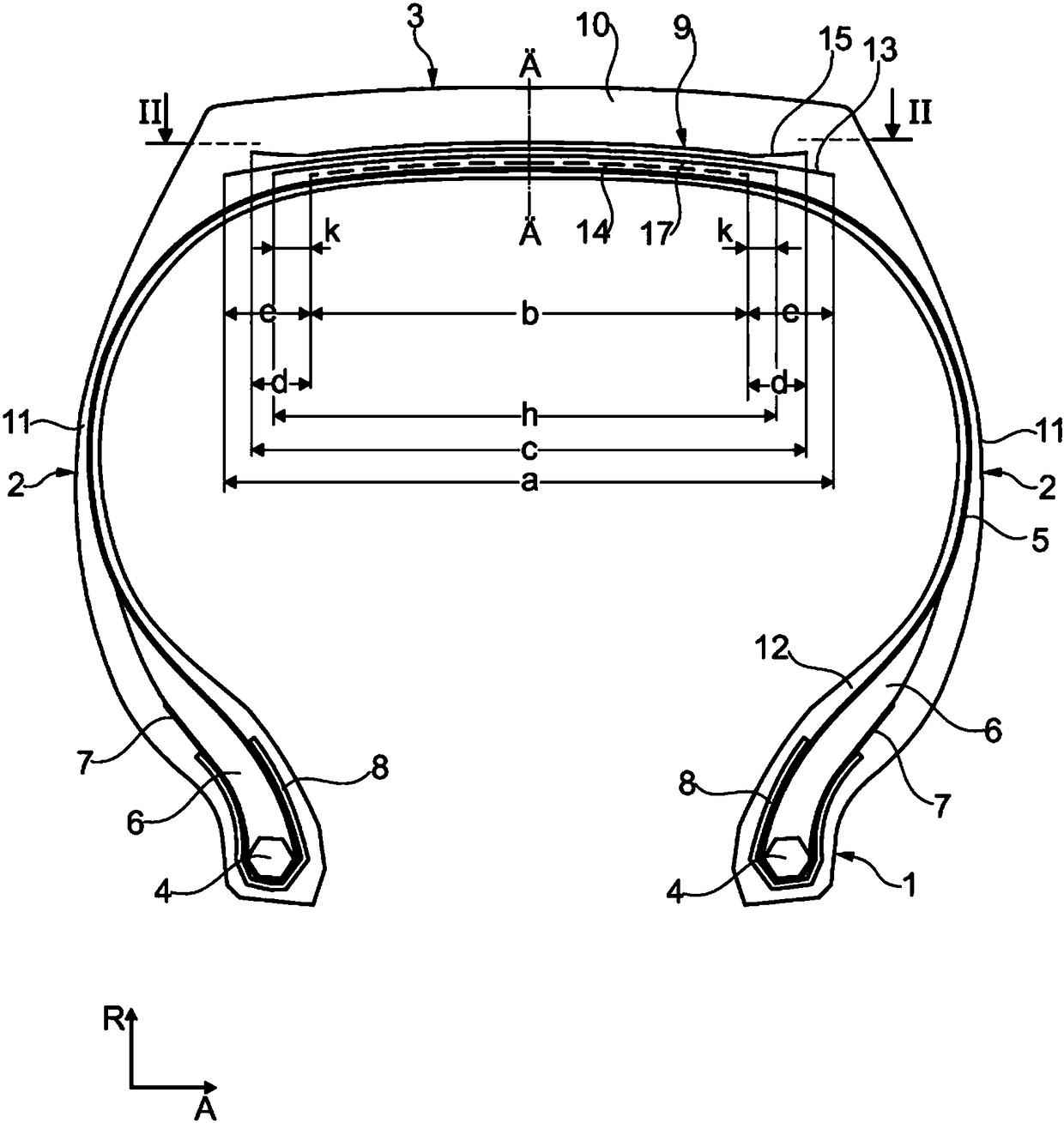
[0025] figure 1 with figure 2 Shown is a pneumatic tire of radial configuration for a utility vehicle having two side walls 2 extending in the radial direction R of the vehicle tire and having axially formed between said side walls The crown area (top area)3. These side walls each have, on their extended ends directed inwards in the radial direction, a bead area 1 in which a bead core 4 of known type is formed, which in the circumferential direction U Has high tensile strength and extends circumferentially over the circumference of the tire. In a known manner, the bead core 4 is formed in a wound manner from a wire, which extends in the circumferential direction U of the pneumatic vehicle tire and is embedded in rubber. An apex (bead filler) 6 that is triangular in cross section is formed on the bead core 4 from a hard rubber material in a conventional manner. The pneumatic vehicle tire is formed with a carcass 5 extending outward across the left-hand side in the radial ...


PUM


Abstract

A pneumatic vehicle tire for a multi-purpose vehicle, having a carcass (5), a belt (9) and a shaped tread (10), the belt (9) consisting of at least four belt layers arranged in a superposed manner from radially inner to outer (14, 17, 13, 15) are formed such that the radially innermost first belt layer (14) has a strength member (24), the second belt layer (17) has a strength member (27), and the third belt layer (17) has a strength member (27). The belt layer (13) has a strength member (23), the fourth belt layer (15) has a strength member (25), wherein the third (13) and the fourth belt layer (15) are working layers, and the third belt layer (15) has a strength member (25). The strength members (23) of the belt layer (13) are oriented to enclose an angle α with the circumferential direction U, 10°≤α≤45°, and the strength members (25) of the fourth belt layer (15) enclose an angle γ, 10°≤γ≤45°, the strength member (23) of the third belt layer (13) has an opposite axial tilt direction relative to the strength member (25) of the fourth belt layer (15), the first The strength members (24) of the belt layer (14) are oriented to enclose an angle β with the circumferential direction U, 0°≤β≤5°, and the strength members (27) of the second belt layer (17) enclose an angle ε, 40°≤ε≤75°.

Description

technical field [0001] The present invention relates to a pneumatic vehicle tire for a utility vehicle, the pneumatic vehicle tire having a carcass, having a belt constructed on the outside in the radial direction of the carcass, and having a belt constructed on the belt A shaped tread radially outer, wherein the belt is formed of at least four belt layers arranged on top of each other from radially inner to radially outer, wherein in the radial direction R The first belt layer arranged on the innermost side is formed with a plurality of parallel strength members embedded in rubber, and the second belt layer arranged on the first belt layer is formed with a plurality of parallel strength members embedded in rubber. strength members, a third belt layer arranged on the second belt layer is formed with parallel strength members embedded in rubber, and a fourth belt layer arranged on the third belt layer forms There are multiple parallel strength members embedded in the rubber. ...

Claims


Application Information

Patent Timeline
Patent Type & Authority Patents(China)
IPC IPC(8): B60C9/20
CPCB60C2200/06B60C9/28B60C9/2006B60C2009/2016B60C2009/2019
Inventor 米哈尔·拉茨科马蒂亚斯·格劳夫法比安·瓦赫曼
Owner CONTINENTAL REIFEN DEUTSCHLAND GMBH
Why Eureka
Try Eureka