Centrifugal pendulum

A centrifugal force pendulum and centrifugal force technology, applied in the field of centrifugal force pendulum, can solve problems such as reduced comfort, and achieve the effect of eliminating the buffer device

Active Publication Date: 2017-02-22
SCHAEFFLER TECH AG & CO KG
View PDF6 Cites 10 Cited by
  • Summary
  • Abstract
  • Description
  • Claims
  • Application Information

AI Technical Summary

Problems solved by technology

The resulting ...

Method used


Image

  • Centrifugal pendulum
  • Centrifugal pendulum
  • Centrifugal pendulum

Examples


Embodiment Construction

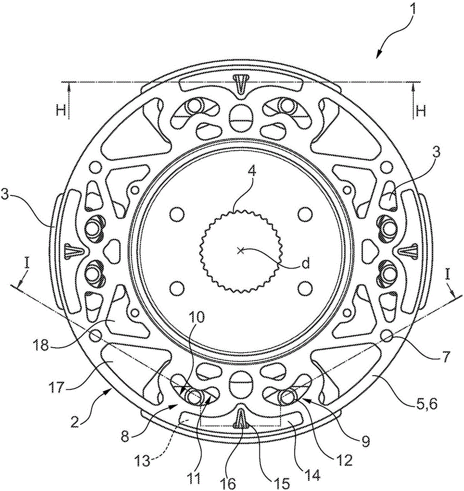
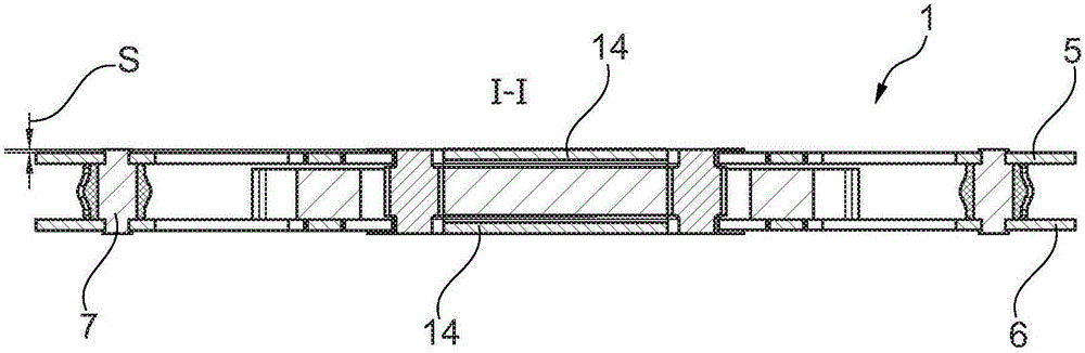
[0020] figure 1 A view is shown of a centrifugal pendulum 1 , which is rotatable about an axis of rotation d, which is mounted, for example, on a clutch disk by means of an internal toothing 4 . The pendulum flange 2 consists of two discs 5, 6 which are spaced apart radially on the outside, are connected to each other by means of spacer pins 7 and contact each other radially on the inside, between which a Pendulums 3 arranged distributed on the circumference. The pendulum 3 is suspended on the pendulum flange 2 on two pivot bearings 8 , 9 each with a predetermined mass and vibration angle that are adapted to the vibration levels of the exciting vibrations, so as to pivot in a centrifugal force field. The pivot bearings 8 , 9 are formed by rolling tracks 10 , 11 , which are formed in cutouts in the disks 5 , 6 and in the pendulum masses, and pendulum rollers 12 each rolling on said rolling tracks.

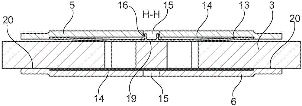
[0021] In order to reduce the axial play between pendulum flange 2 and pendu...


PUM


Abstract

The invention relates to a centrifugal pendulum (1) comprising a pendulum flange (2) that is rotatable about an axis of rotation (d), and pendulums (3) which are distributed along the circumference and are suspended in the pendulum flange (2) so as to oscillate within the centrifugal field of the rotating pendulum flange (2). In order to prevent the pendulums (3) from striking the pendulum flange (2) hard, the pendulums (3) are axially biased relative to the pendulum flange (2).

Description

technical field [0001] The invention relates to a centrifugal pendulum having a pendulum flange which is rotatable about an axis of rotation and a pendulum which is distributed over the circumference and is suspended in the pendulum flange so as to pivot in the centrifugal force field of the rotating pendulum flange. Background technique [0002] The centrifugal pendulum serves to reduce torsional vibrations and comprises a pendulum flange that is rotatable about an axis of rotation and a pendulum with a preadjusted mass. When the pendulum is excited by rotational speed inhomogeneities, which are introduced, for example, by an internal combustion engine of a drive train of a motor vehicle with torsional vibrations, the pendulum travels on a predetermined path in the centrifugal acceleration field Implement vibration. These vibrations extract energy from the excitation vibrations of the rotational inhomogeneity when the torque increases and re-supply energy when the torque d...

Claims


Application Information

Patent Timeline
IPC IPC(8): F16F15/14
CPCF16F15/145
Inventor A·鲁施A·杜施夫S·莱曼
Owner SCHAEFFLER TECH AG & CO KG
Why Eureka
Try Eureka