Drawing method and apparatus for graphic user interface (GUI)

A graphical user interface and drawing unit technology, applied in the field of communication, can solve problems such as low program execution efficiency, and achieve the effect of improving execution efficiency

Inactive Publication Date: 2017-03-01
ZTE CORP
View PDF0 Cites 8 Cited by
  • Summary
  • Abstract
  • Description
  • Claims
  • Application Information

AI Technical Summary

Benefits of technology

The technical effects of this patented method include that it allows users to efficiently create computer programs without having to manually analyze them when they want their interface or how well they work on different screens. This makes programming faster than traditional methods like scripted languages can be done at once.

Problems solved by technology

This patented technical problem addressed in this patents relates to selecting an appropriate graphic supporting system for various types of embedded devices that have varying hardware configuration and operation modes without requiring extensive modifications or costly licensings from experts at both ends.

Method used


Image

  • Drawing method and apparatus for graphic user interface (GUI)
  • Drawing method and apparatus for graphic user interface (GUI)
  • Drawing method and apparatus for graphic user interface (GUI)

Examples


Embodiment Construction

[0023] Hereinafter, the present invention will be described in detail with reference to the drawings and examples. It should be noted that, in the case of no conflict, the embodiments in the present application and the features in the embodiments can be combined with each other.

[0024] It should be noted that the terms "first" and "second" in the description and claims of the present invention and the above drawings are used to distinguish similar objects, but not necessarily used to describe a specific sequence or sequence.

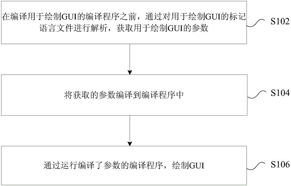
[0025] A method for drawing a graphical user interface GUI is provided in this embodiment, figure 1 It is a flowchart of a drawing method of a graphical user interface GUI according to an embodiment of the present invention, such as figure 1 As shown, the process includes the following steps:

[0026] Step S102, before compiling the compiling program for drawing the GUI, by parsing the markup language file for drawing the GUI, obtaining parameters fo...


PUM


Abstract

The invention provides a drawing method and apparatus for a graphic user interface (GUI). Through the drawing method and apparatus, before a compilation program used for drawing the GUI is compiled, a markup language file used for drawing the GUI is analyzed to obtain parameters used for drawing the GUI; the obtained parameters are compiled in the compilation program; and the GUI is drawn by running the compilation program subjected to parameter compilation . The problem of low program execution efficiency caused by the fact that the parameters used for drawing the GUI need to be analyzed in the compilation process in related technologies is solved, so that the effect of improving the executive efficiency of the program used for drawing the GUI is achieved.

Description


Claims


Application Information

Patent Timeline
Owner ZTE CORP
Why Eureka
Try Eureka