Check patentability & draft patents in minutes with Patsnap Eureka AI!

Split type interchange common overpass structure

A split and ordinary technology, applied in roads, roads, buildings, etc., to achieve the effect of low cost, simple structure, and less land occupation

Active Publication Date: 2017-03-29
SHANXI PROVINCIAL RES INST OF COMM +1
View PDF5 Cites 0 Cited by
  • Summary
  • Abstract
  • Description
  • Claims
  • Application Information

AI Technical Summary

Problems solved by technology

[0003] The purpose of the present invention is to aim at the defect of existing urban road traffic structure, thereby provide a kind of flexible, applicable, the split type intercommunication common overpass structure that is used for urban road intersection, is exactly by the design to the traveling route of each direction, combines The special left-turn short road on the ground between the two bridges forms a traffic route network of split interchange overpasses to realize the smooth passage of vehicles traveling in all directions at the intersection

Method used


Image

  • Split type interchange common overpass structure
  • Split type interchange common overpass structure
  • Split type interchange common overpass structure

Examples


Embodiment 1

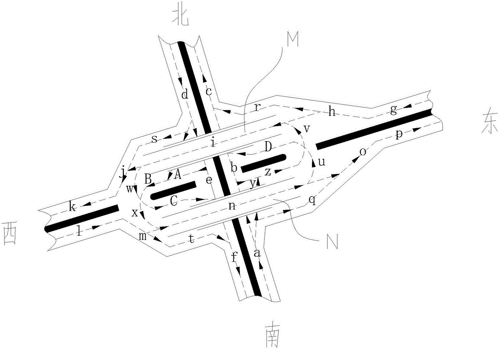
[0019] Such as figure 1 The structure shown is a split-type intercommunication ordinary interchange structure based on a cross-shaped intersection structure, including a split-type one-way ordinary overpass and a cross-shaped intersection formed by two vertical and horizontal general roads. The split-type one-way ordinary The overpass bridge is placed above the longitudinal general road and communicated with the horizontal general road.

[0020] Wherein, the split-type one-way ordinary overpass is composed of two parallel one-way ordinary overpasses, and the two one-way ordinary overpasses are respectively connected with two one-way lanes of the transverse ordinary road.

[0021] There is an appropriate distance between these two ordinary overpasses with the center line of the horizontal general road moved longitudinally to both sides, thereby forming a left-turn special site symmetrical to the center line of the intersecting road. Wherein, the split type one-way ordinary ove...

Embodiment 2

[0035] Since in the left-turn area in Embodiment 1, left-turn vehicles from all directions will interweave and tie knots in this area, this situation is applicable to the situation with less traffic flow.

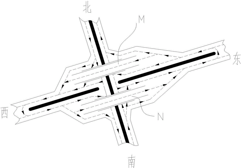
[0036] If the traffic flow in the left-turn area is very large, then the left-turn vehicle of the above-mentioned embodiment will be blocked, therefore, as the improvement of the above-mentioned embodiment, the weaving area can be lengthened, as figure 2 As shown, the above-mentioned problems can be solved, or a roundabout is arranged at the connection position between the split-type interchange common overpass and the general road, so that the above-mentioned problems can be alleviated.

[0037] The split-type intercommunication general overpass structure of the present invention is formed by two parallel common overpass bridges, combined with four special left-turn curves on the ground between the two bridges and other combined routes; it realizes that vehicles traveling ...


PUM


Abstract

The invention relates to a split type interchange common overpass structure. A crossroad structure is used as the establishment foundation of the split type interchange common overpass structure. The split type interchange common overpass structure comprises two split type parallel one-way common overpasses and a crossroad, wherein the crossroad is composed of a longitudinal common road and a transverse common road. The split type one-way common overpasses are arranged above the longitudinal common road or the transverse common road. The two parallel one-way common overpasses are connected with two one-way lanes of the transverse common road or the longitudinal common road. A left-turn dedicated site is arranged between the two common overpasses, wherein the left-turn dedicated site is formed in the manner that lanes of the transverse common road or the longitudinal common road connected with the two common overpasses are longitudinally or transversely moved from the center line of the transverse common road or the longitudinal common road to the two sides by an appropriate distance, and the left-turn dedicated site is symmetrical about the central lines of the intersecting roads. The split type interchange common overpass structure achieves that traveling vehicles in all directions of the crossroad travel in own lanes and smoothly pass the crossroad. The split type interchange common overpass structure has the adjusting and guiding functions and achieve infinite circulation of vehicles travelling in the overpass area.

Description

technical field [0001] The invention relates to an urban traffic road structure, in particular to a split-type intercommunicating common overpass structure based on a cross-shaped intersection structure. Background technique [0002] In order to solve urban traffic jams at present, multiple solutions have occurred, generally having the following situations. The first kind is that the overpass bridge has many storeys, and the erection is relatively high so that the slope is long or the slope is large, the floor area is wide, and the investment is large, which is unrealistic. The second is to use a longer viaduct or drop-down trough, although not too high, but only to alleviate local traffic congestion. The third is to drive through the limited number, but with the continuous increase of vehicles, the limited number cannot finally solve the congestion of urban traffic. The last is to build subways or light rails, but they can only solve the problem of smooth flow in general ...

Claims


Application Information

Patent Timeline
Patent Type & Authority Applications(China)
IPC IPC(8): E01C1/04
CPCE01C1/04
Inventor 韩之江杨子政白鸿莲赵雷宋庆瑞李元军杨凯韩颖异汪永强刘志华郭文龙谢立安
Owner SHANXI PROVINCIAL RES INST OF COMM
Features
  • R&D
  • Intellectual Property
  • Life Sciences
  • Materials
  • Tech Scout
  • Unparalleled Data Quality
  • Higher Quality Content
  • 60% Fewer Hallucinations
Learn More