
Fuel injector

A technology of fuel injectors and injectors, applied in fuel injection devices, special fuel injection devices, charging systems, etc., can solve the problems of costly manufacturing and achieve the effect of economical manufacturing

Active Publication Date: 2017-05-10
ROBERT BOSCH GMBH
View PDF4 Cites 0 Cited by
  • Summary
  • Abstract
  • Description
  • Claims
  • Application Information

AI Technical Summary

Problems solved by technology

However, the use of two separate components also requires relatively complex production

Method used


Image

  • Fuel injector
  • Fuel injector
  • Fuel injector

Examples


Embodiment Construction

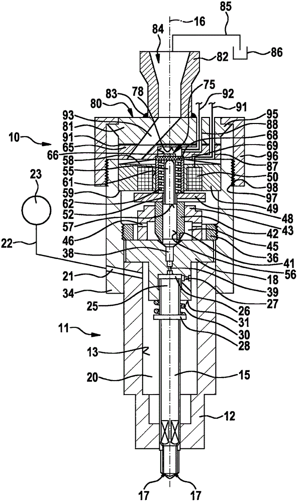
[0021] figure 1 The illustrated fuel injector 10 according to the invention is a component part of a common rail injection system for injecting fuel into a combustion chamber, in particular of a self-igniting internal combustion engine. The fuel injector 10 has an injector housing 11 which includes a nozzle body 12 on the side facing the not shown combustion chamber of the internal combustion engine. The cylindrical nozzle body 12 has a recess 13 in which the nozzle needle 15 is arranged movable up and down along the longitudinal axis 16 of the injector housing 11 in order to be closed or open on the bottom or in the wall of the nozzle body 12 The injection opening 17.

[0022] The side of the recess 13 of the nozzle body 12 facing away from the injection opening 17 is closed by a valve block 18 such that the recess 13 forms a high-pressure chamber 20 or high-pressure region for the fuel. The high-pressure chamber 20 is connected in particular to a storage element 23 configu...


PUM


Abstract

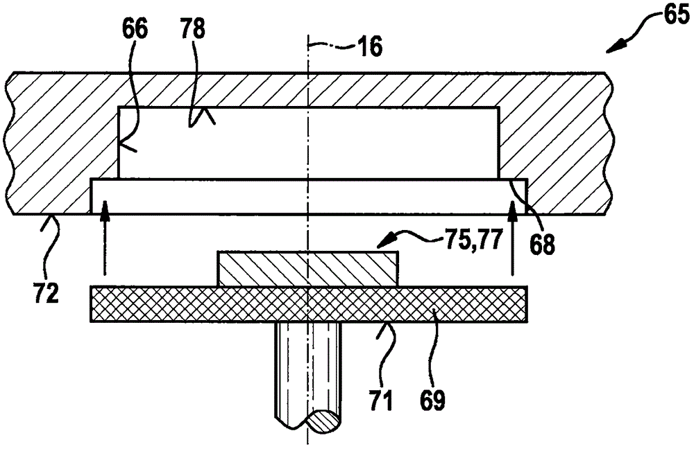
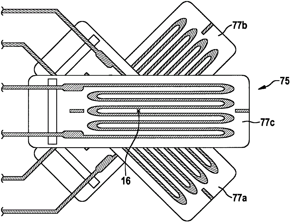
The invention relates to a fuel injector (10), in particular a common-rail injector for self-igniting internal combustion engines, comprising an injector housing (11) in which a sensor element is arranged in a low-pressure region (45) for at least indirectly detecting a fuel pressure prevailing in a high-pressure region (20), the sensor element resting against an elastically deformable sealing element (69) on the side remote from the high-pressure region (20), said sealing element sealing a receiving space (66) for the sensor element. According to the invention, the sensor element is designed in the form of a force sensor (75) having at least one strain measuring element, the force sensor (75) being connected to the sealing element (69).

Description

technical field [0001] The invention relates to a fuel injector according to the preamble of claim 1 . Background technique [0002] A fuel injector of this type is known from the applicant's patent document DE 10 2010 044 012 A1. In known fuel injectors, the sensor element in the form of a pressure sensor is arranged in a blind hole-like recess of the sensor plate, wherein the pressure sensor is located in the recess on the side facing away from the sensor plate by means of a membrane, in particular made of metal. Covered or protected, the membrane is formed as a sealing element. In addition to the force transmission of the transmission element coupled to the armature, the known sealing element also serves to prevent fuel from penetrating into the recess. A disadvantage of the known fuel injectors is that, due to the configuration of the contact surface for the pressure sensor in a recess on the bottom of the sensor plate, a relatively complex and therefore cost-intensive...

Claims


Application Information

Patent Timeline
IPC IPC(8): F02M57/00F02M47/02
CPCF02M47/027F02M57/005F02M2200/16F02M2200/244F02M2200/247
Inventor H·拉普W·施特克莱茵B·贝格黑内尔M·拜尔S·施泰因
Owner ROBERT BOSCH GMBH
Learn More