Unmanned aerial vehicle signal enhancement antenna structure

A technology of antenna structure and signal enhancement, applied in the direction of antenna, radiating element structure, electrical components, etc., can solve the problems of untimely steering of the control direction and insufficient control distance, and achieve the effect of ensuring the control distance

Pending Publication Date: 2017-05-24
SHENZHEN TIANDING MW TECH CO LTD
View PDF0 Cites 1 Cited by
  • Summary
  • Abstract
  • Description
  • Claims
  • Application Information

AI Technical Summary

Problems solved by technology

[0005] The main purpose of the present invention is to provide a foldable unmanned aerial vehicle signal enhancement antenna structure, aiming to solve the technical problems of insufficient control distance and untimely control direction steering faced by unmanned aerial vehicles during long-distance flight

Method used


Image

  • Unmanned aerial vehicle signal enhancement antenna structure
  • Unmanned aerial vehicle signal enhancement antenna structure
  • Unmanned aerial vehicle signal enhancement antenna structure

Examples


Embodiment Construction

[0020] The specific implementation of the foldable UAV signal enhancement antenna structure provided by the present invention will be described in detail below in conjunction with the accompanying drawings.

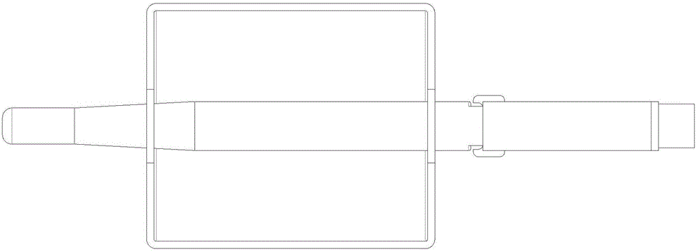
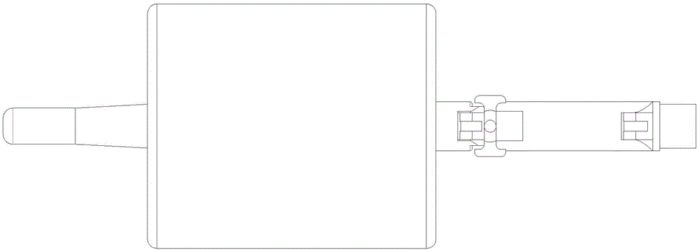
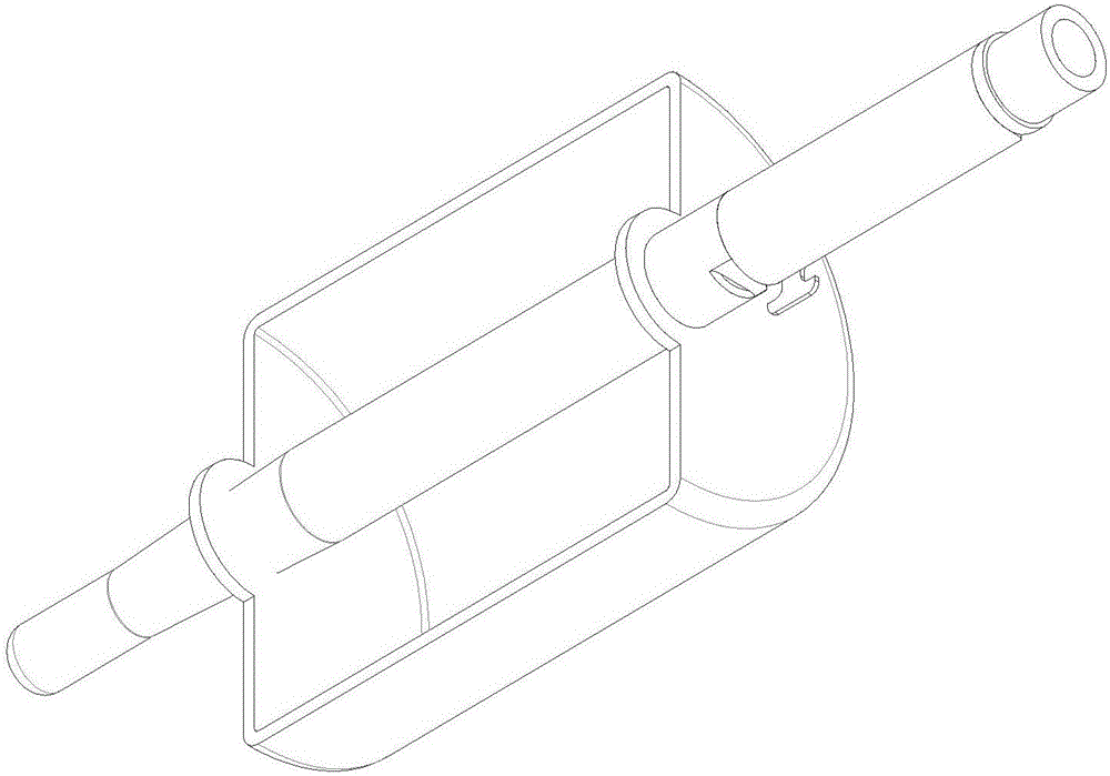
[0021] Such as Figure 1-4 As shown, the foldable unmanned aerial vehicle signal enhancement antenna structure includes a class I steering mechanism 1, a class II steering mechanism 2, a class II steering locking mechanism 3, an antenna main body mechanism 4, and a parabolic amplifying plate 5. The parabolic amplifying plate 5 has front and rear Two holes, one end of the antenna body mechanism 4 is inserted into the copper-plated parabolic amplifying plate 5 through the front and rear holes, and the other end of the antenna body mechanism 4 and one end of the II-level steering mechanism 2 pass through the II-level steering locking mechanism 3 The other end of the II-level steering mechanism 2 is connected with the I-level steering mechanism 1 again. The parabolic amplify...


PUM


Abstract

The present invention discloses an unmanned aerial vehicle signal enhancement antenna structure. The antenna structure comprises an I-grade steering mechanism, an II-grade steering mechanism, an II-grade steering lock mechanism, an antenna main body mechanism and a parabola amplification board. The parabola amplification board has two holes at the front and the back, one end of the antenna main body mechanism runs through the parabola amplification board through the holes at the front and the back, the other end of the antenna main body mechanism is connected with one end of the II-grade steering mechanism through the II-grade steering lock mechanism, and the other end of the II-grade steering mechanism is connected with the I-grade steering mechanism. The foldable parabola unmanned aerial vehicle signal enhancement antenna structure can ensure that the enhancement of the antenna control distance of the unmanned aerial vehicle and timely and rapidly change the orientation of the antenna to allow the unmanned aerial vehicle to be always in the remote controller range.

Description

technical field [0001] The invention relates to the field of unmanned aerial vehicles, in particular to a foldable parabolic unmanned aerial vehicle signal enhancement antenna structure. Background technique [0002] At present, it is widely used in civil, commercial and other fields. More for extreme sports, for reporting on various sports events, for the logistics industry, for shooting enthusiasts and wider market prospects, as a new thing with an increasing audience, in order to protect drones In the tide of wide application, it is safer and more reliable, and drone antennas have broad development prospects. [0003] When UAVs fly in the air, they will encounter emergencies such as weather, clouds, and strong winds. Especially for UAVs that can fly for a long time, it is more necessary to enhance the remote control of the signal, and to be able to launch / receive UAVs in time Antenna design for flight direction command. [0004] The above content is only used to assist...

Claims


Application Information

Patent Timeline
Patent Type & Authority Applications(China)
IPC IPC(8): H01Q3/08H01Q1/36
CPCH01Q3/08H01Q1/36
Inventor 周涛江荣龙向广
Owner SHENZHEN TIANDING MW TECH CO LTD
Why Eureka
Try Eureka