Additive manufacturing apparatus and methods

a technology of additive manufacturing and energy beam, which is applied in the direction of additive manufacturing processes, manufacturing tools, instruments, etc., can solve the problems of significant divergence of laser beam from desired patterns, warping and/or curling of parts being built, and difficult drag of melt pool across the layer in a continuous mode of laser operation, so as to achieve fast dynamic response, fast magnetic field change, and fast dynamic response

Active Publication Date: 2018-02-08
RENISHAW PLC
View PDF1 Cites 6 Cited by
  • Summary
  • Abstract
  • Description
  • Claims
  • Application Information

AI Technical Summary

Benefits of technology

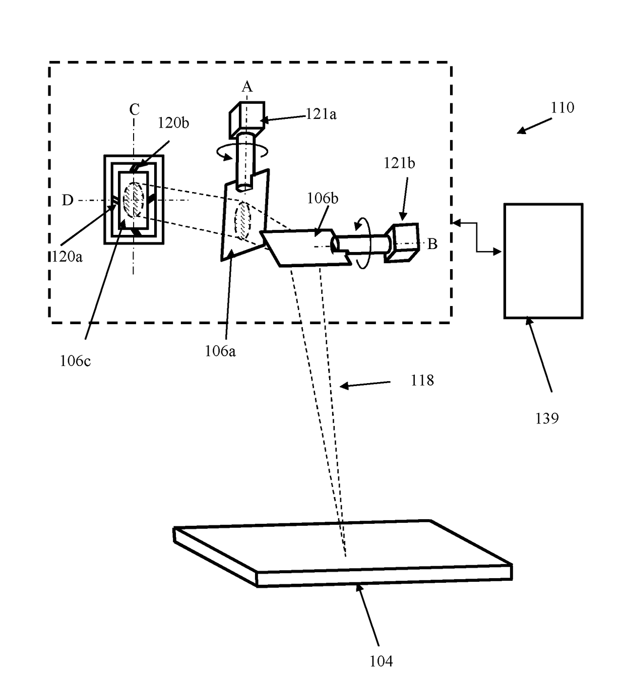
[0013]In this way, the scanner can deflect the energy beam over a large range of angles in the first dimension whilst achieving rapid changes in direction unachievable using the first beam steering component alone. The dynamic capability of the scanner may allow the energy beam to be scanned along paths closer to the ideal scanning strategies, such as those described above.
[0028]According to a second aspect of invention there is provided an additive manufacturing apparatus comprising a build chamber, a build platform lowerable in the build chamber such that layers of flowable material can be successively formed across the build platform, a radiation generator for generating an energy beam and a scanner for directing the energy beam onto each layer to selectively solidify the material, the scanner comprising a beam steering component operable for deflecting the energy beam over a first range of angles in a first dimension and a second beam steering component for deflecting the energy beam over a second range of angles in the first dimension, wherein the second beam steering component provides a faster dynamic response but a smaller range of movement than the first beam steering component.

Problems solved by technology

Excessive, unrestrained thermal loads created during the build cause warping and / or curling of the part being built.
For some materials, such as tool steels and aircraft grade super alloys, it can be difficult to drag the melt pool across the layer in a continuous mode of operation of the laser.
The limited dynamic response of the galvanometers can result in significant divergence of the laser beam from the desired patterns (as described above).
However, the dynamic response of the galvanometers is too slow relative to desired point exposure times and time between exposures such that the mirrors will still be moving during an exposure.
Such problems can be overcome by increasing the time between exposures in order to give the mirrors time to move to and settle in the new position but this can significantly lengthen the build time.
A problem with the electro and acoustic optical deflectors is that the deflectors absorb a significant proportion of the light travelling therethrough.
Accordingly, such deflectors are unsuitable for use with high power laser beams because of the resultant heating of the deflector that would occur.
Such heating would make it extremely difficult, if not impossible, to control the temperature of the crystals of the deflector to be just above the Curie temperature, as required.

Method used


Image

  • Additive manufacturing apparatus and methods
  • Additive manufacturing apparatus and methods
  • Additive manufacturing apparatus and methods

Examples


Embodiment Construction

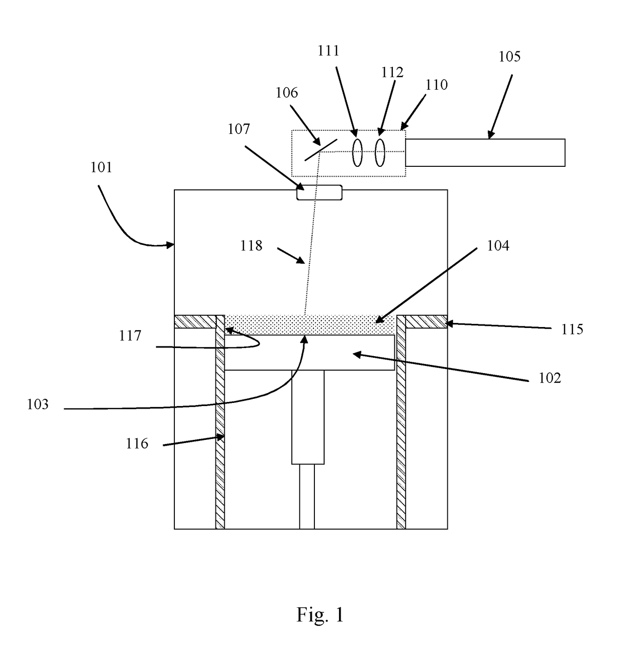
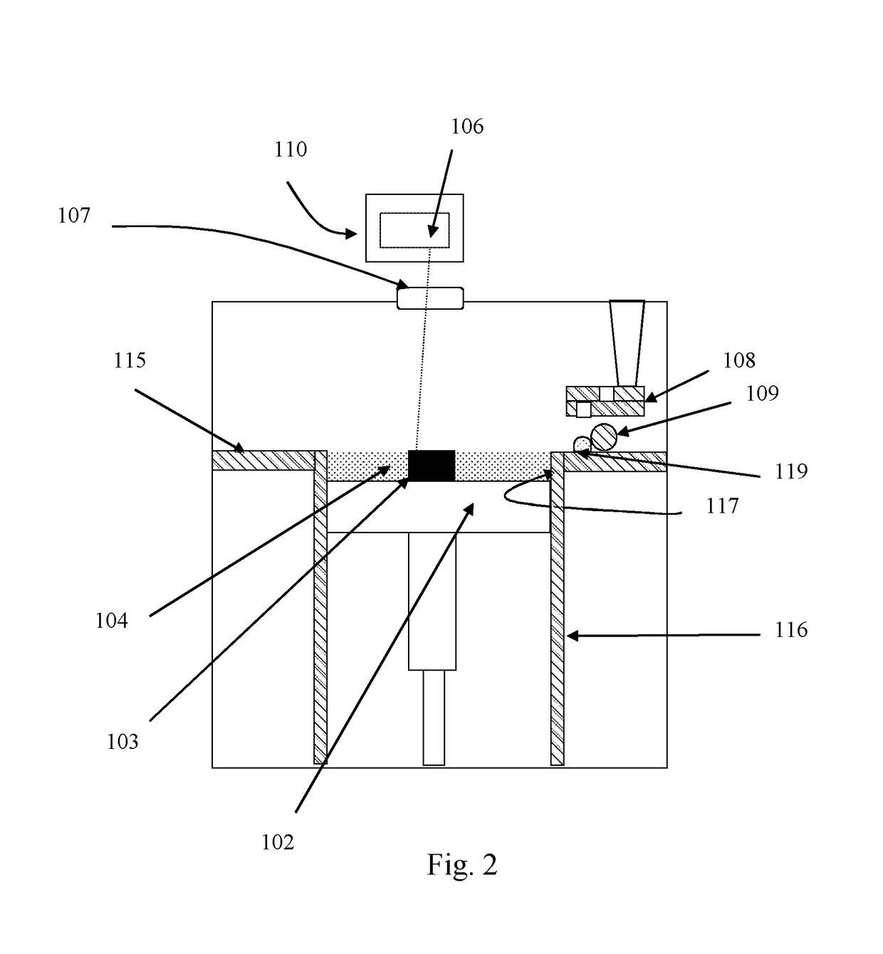
[0045]Referring to FIGS. 1 and 2, a laser solidification apparatus according to an embodiment of the invention comprises a main chamber 101 having therein partitions 115, 116 that define a build chamber 117 and a surface onto which powder can be deposited. A build platform 102 is provided for supporting an object 103 built by selective laser melting powder 104. The platform 102 can be lowered within the build chamber 117 as successive layers of the object 103 are formed. A build volume available is defined by the extent to which the build platform 102 can be lowered into the build chamber 117.

[0046]Layers of powder 104 are formed as the object 103 is built by dispensing apparatus 108 and an elongate wiper 109. For example, the dispensing apparatus 108 may be apparatus as described in WO2010 / 007396.

[0047]A laser module 105 generates a 500 W laser for melting the powder 104, the laser directed as required by a scanner, in this embodiment an optical module 110, under the control of a c...


PUM

PropertyMeasurementUnit
anglesaaaaaaaaaa
anglesaaaaaaaaaa
stressaaaaaaaaaa

Abstract

An additive manufacturing apparatus including a scanner for directing a laser beam on to layers of flowable material to selectively solidify the material to form an object in a layer-by-layer manner. The scanner includes an optical component operable under the control of a first actuator to reflect the laser beam over a first range of angles in a first dimension and the or a further optical component operable under the control of a second actuator to reflect the laser beam over a second range of angles in the first dimension, wherein the second actuator provides a faster dynamic response but a smaller range of movement of the laser beam than the first actuator.

Description

FIELD OF INVENTION[0001]This invention concerns a scanner and method for directing an energy beam in an additive manufacturing apparatus, in which layers of material are solidified in a layer-by-layer manner to form an object. The invention has particular, but not exclusive application, to selective laser solidification apparatus, such as selective laser melting (SLM) and selective laser sintering (SLS) apparatus.BACKGROUND[0002]Selective laser melting (SLM) and selective laser sintering (SLS) apparatus produce objects through layer-by-layer solidification of a material, such as a metal powder material, using a high energy beam, such as a laser beam. A powder layer is formed across a powder bed in a build chamber by depositing a heap of powder adjacent to the powder bed and spreading the heap of powder with a wiper across (from one side to another side of) the powder bed to form the layer. A laser beam is then scanned across areas of the powder layer that correspond to a cross-secti...

Claims


Application Information

Patent Timeline
Patent Type & Authority Applications(United States)
IPC IPC(8): B29C64/153G02B26/00B33Y30/00B33Y40/00B29C64/20B33Y10/00
CPCB29C64/153B29C64/20B33Y10/00B33Y30/00B33Y40/00G02B26/00B23K26/082B23K26/342G02B26/02G02B26/10B22F12/44B22F12/49B22F10/28B22F10/366G02B26/101B33Y50/02B29C64/393B29C64/264B29C64/268Y02P10/25
Inventor BROWN, CERIJONES, NICHOLAS H HEWING, DAVID G JMCFARLAND, GEOFFREY
Owner RENISHAW PLC
Why Eureka
Try Eureka