Bobbin limiting mechanism

A limit mechanism and bobbin technology, applied in the direction of conveyor objects, transportation and packaging, etc., can solve the problem of not being able to arrange the bobbins in the same direction, and achieve the effects of simple structure, reduced manual participation, and high accuracy

Active Publication Date: 2017-05-31
苏州斯米图智能科技有限公司
View PDF9 Cites 5 Cited by
  • Summary
  • Abstract
  • Description
  • Claims
  • Application Information

AI Technical Summary

Problems solved by technology

[0003] In order to solve the problem that the bobbin sorting device in the prior art cannot arrange the bobbins in the sam

Method used


Image

  • Bobbin limiting mechanism
  • Bobbin limiting mechanism
  • Bobbin limiting mechanism

Examples


Embodiment Construction

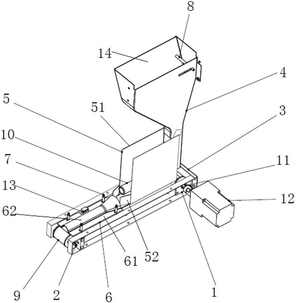
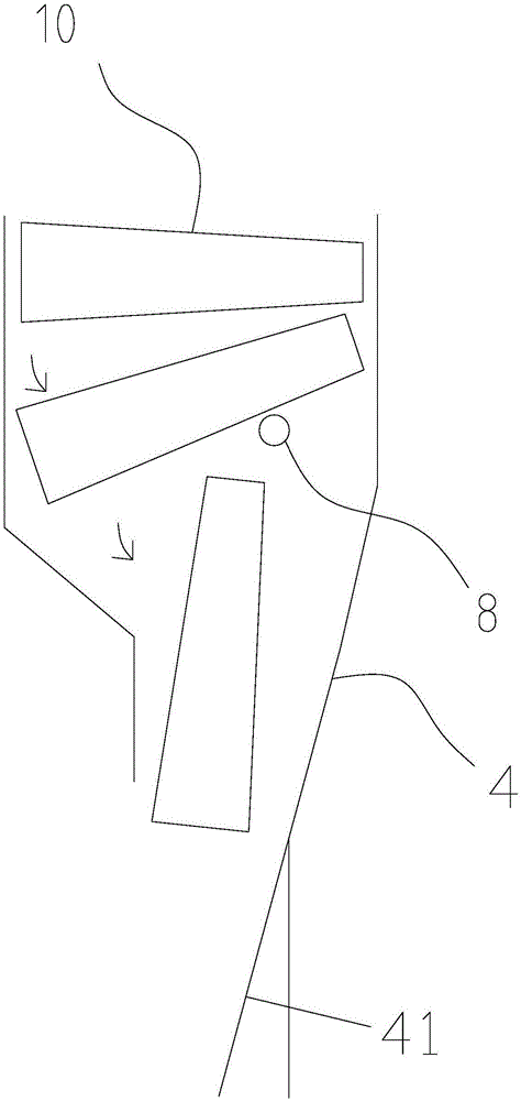
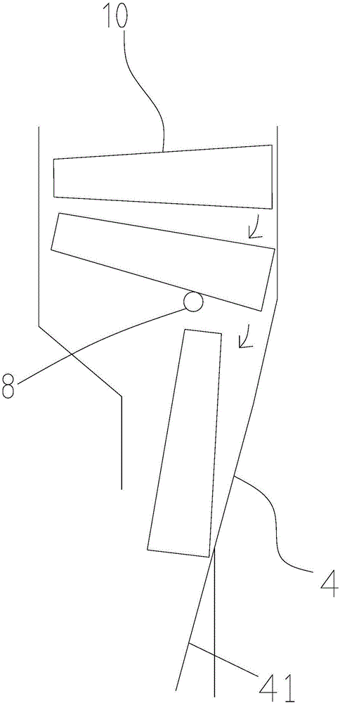
[0021] like figure 1 , a yarn bobbin limiting mechanism, the diameters of the two ends of the yarn bobbin 10 are inconsistent, and the two ends are respectively a large end and a small end. A slope for the yarn supply bobbin 10 to slide down is provided in the feed opening, a bobbin turn-around rod 8 is provided between the slope and the inner wall of the hopper opposite to the slope, and a bobbin channel 4 for vertically falling the bobbin 10 is provided below the hopper, and the yarn A discharge mechanism is connected below the tube channel 4 . The feeding opening is rectangular, the bobbin passage 4 is located on the side below the feeding opening, and the bobbin turning-back lever 8 is located on the side close to the bobbin passage 4 .

[0022] Below the bobbin channel 4 is provided a guiding slope 41 that guides the bobbin 10 to the discharge mechanism. The discharge mechanism includes a transmission belt 9 arranged in a horizontal direction. The end of the transmissio...


PUM


Abstract

The invention relates to the technical field of textile machinery, in particular to a bobbin limiting mechanism. The diameters of the two ends of each bobbin are unequal, and the two ends are a big end and a small end correspondingly. The limiting mechanism comprises a support. A hopper is arranged on the support. A feeding inlet is formed in the upper end of the hopper. A slope allowing bobbins to slide down is arranged in the feeding inlet. A bobbin turning rod is arranged between the slope and the inner wall, opposite to the slope, of the hopper. A bobbin channel allowing the bobbins to drop down vertically is arranged under the hopper. The lower portion of the bobbin channel is connected with a discharging mechanism. Through the limiting mechanism, the bobbins can fall into a bobbin basket orderly in the mode that the bobbins are consistent in the directions of the big ends and the small ends, manual intervention is avoided or reduced to the greatest extent, and pause of a machine for the next procedure is reduced or eliminated.

Description

technical field [0001] The invention relates to the technical field of textile machinery, in particular to a bobbin limiting mechanism. Background technique [0002] In the prior art, the empty yarn bobbins dropped from the winding machine enter the bobbin basket in a disorderly manner, and the work of arranging the bobbins is all done manually, which requires a large amount of labor and low work efficiency. In the current situation of high labor costs It has become a big burden for textile enterprises. The patent No. CN200920104558.9 discloses a bobbin finishing device, which uses a color sensor to identify bobbins with and without bobbins. The patent No. CN201420524342.9 discloses a bobbin finishing machine that achieves precise Separation has yarn bobbins, but the structure of some bobbins is that one end is a large end and the other end is a small end, and the existing device cannot arrange the bobbins according to the consistent direction of the big and small ends. S...

Claims


Application Information

Patent Timeline
IPC IPC(8): B65G47/14
CPCB65G47/14
Inventor 边继东戴曦东
Owner 苏州斯米图智能科技有限公司
Why Eureka
Try Eureka