A device for removing low-melting-point alloys in the inner cavity of a blade

A low-melting, in-blade technology, applied in stators, engine components, machines/engines, etc., can solve problems such as residual and residual low-melting alloys, and achieve the effect of reducing removal time and improving work efficiency

Active Publication Date: 2018-05-08
CHINA HANGFA SOUTH IND CO LTD
View PDF5 Cites 0 Cited by
  • Summary
  • Abstract
  • Description
  • Claims
  • Application Information

AI Technical Summary

Problems solved by technology

Since the low-melting-point alloy and the hot oil will be mixed together during the melting process of the low-melting-point alloy, when the guide vane 1 is taken out, the hot oil may remain in the cavity channel of the airfoil 12, thereby lead to residual low melting point alloy

Method used


Image

  • A device for removing low-melting-point alloys in the inner cavity of a blade
  • A device for removing low-melting-point alloys in the inner cavity of a blade
  • A device for removing low-melting-point alloys in the inner cavity of a blade

Examples


Embodiment Construction

[0014] In order to have a clearer understanding of the technical features, purposes and effects of the present invention, the specific implementation manners of the present invention will now be described with reference to the accompanying drawings. Wherein, the same parts adopt the same reference numerals.

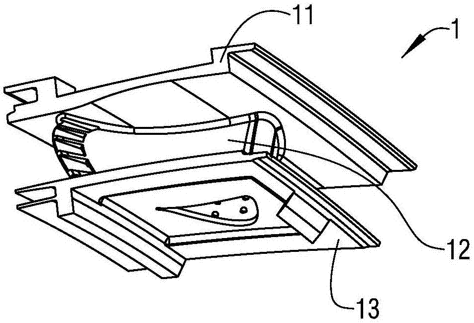
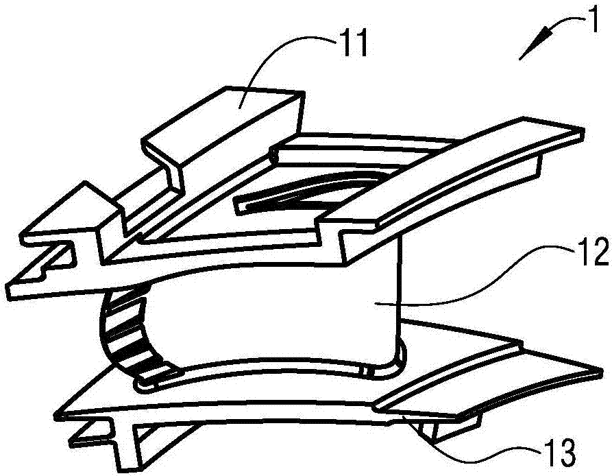
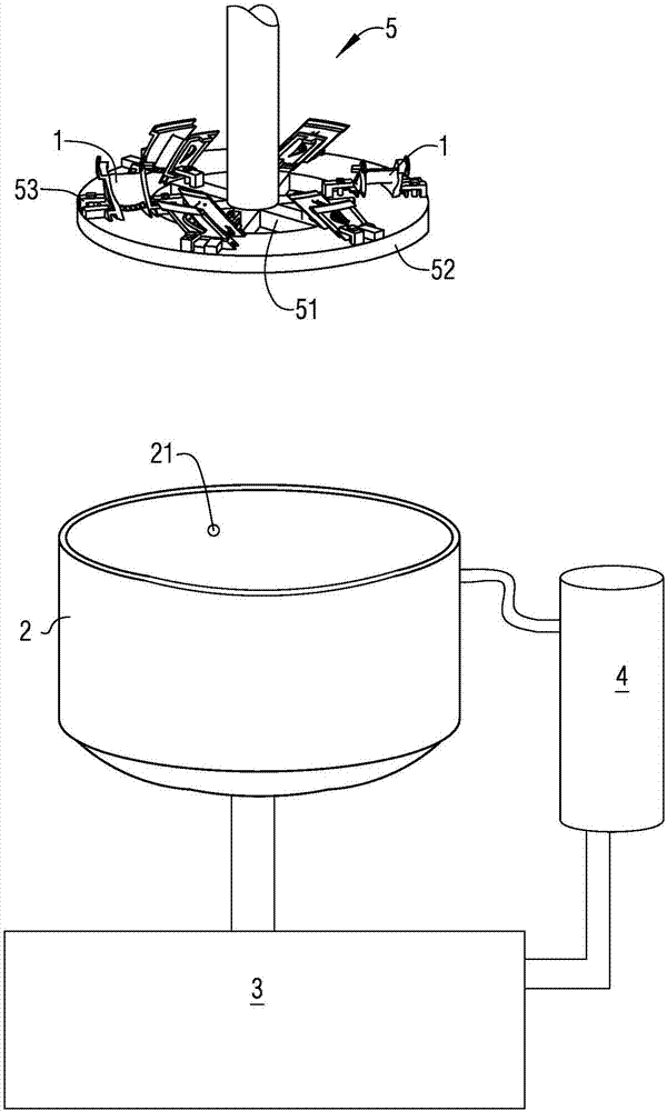
[0015] figure 1 It is a structural schematic diagram of a guide vane of a gas turbine engine; figure 2 for another angle figure 1 Schematic diagram of the structure of the guide vane; image 3 It is a schematic diagram of the structure and principle of a device for removing low-melting-point alloys in the inner cavity of a blade according to a specific embodiment of the present invention. see Figure 1-3 As shown, the present invention provides a device for removing low-melting-point alloys in the inner cavity of a blade. The blade 1 is composed of an outer edge plate 11, a blade body 12, and an inner edge plate 13. The blade body 12 is provided with a trailing edge ...


PUM

PropertyMeasurementUnit
melting pointaaaaaaaaaa

Abstract

The invention discloses a device for removing low-melting-point alloy from the inner cavity of a blade. The device comprises an oil tank; the bottom of the oil tank is connected with a cooling tank through a pipeline with a valve; the cooling tank is connected with a heater with an oil pump through a pipeline; a spraying opening is formed in the side wall of the oil tank; a mounting disc which can lift and rotate is arranged above the oil tank; the mounting disc comprises a mounting ring which is connected through supporting ribs; the mounting ring is provided with a plurality of groups of mounting frames which are used for clamping blades; after the blades are clamped by the mounting frames, the overall height of the mounting ring and the blades thereon is 1 / 10 of the height of the oil tank. According to the device for removing the low-melting-point alloy from the inner cavity of the blade provided by the invention, on one hand, the low-melting-point alloy removal time is effectively shortened, and on the other hand, no residue on the inner cavity of the blade which is subjected to a removal operation is also effectively guaranteed; in addition, a low-melting-point alloy removing operation can be performed continuously in batches; the work efficiency is greatly improved.

Description

technical field [0001] The invention relates to the technical field of engines, in particular to a device for removing low-melting-point alloys from the inner cavity of a hollow guide vane of a gas turbine engine. Background technique [0002] figure 1 It is a structural schematic diagram of a guide vane of a gas turbine engine, figure 2 for another angle figure 1 Schematic diagram of the structure of the guide vane, see Figure 1-2 As shown, the guide vane 1 is composed of three parts: an outer edge plate 11, a blade body 12, and an inner edge plate 13. The blade body 12 is provided with a trailing edge hole, and the middle part of the outer edge plate 11 is provided with an outer edge cavity. The middle part of the inner edge plate 13 is provided with an inner edge cavity, and the blade body 12 is provided with a cavity channel connecting the trailing edge hole, the outer edge cavity, and the inner edge cavity, [0003] In the process of processing the outer edge plat...

Claims


Application Information

Patent Timeline
Patent Type & Authority Patents(China)
IPC IPC(8): F01D9/02B22D31/00
CPCB22D31/00F01D9/02
Inventor 张华谢俊强白启润
Owner CHINA HANGFA SOUTH IND CO LTD
Why Eureka
Try Eureka