Drainage device for draining water from roof

A drainage device and house row technology, which is applied in the direction of roof drainage, roofing, roof covering, etc., and can solve the problems of inconvenient discharge, mixing, and blockage of impurities

Inactive Publication Date: 2021-04-27
胡泽尧
View PDF8 Cites 0 Cited by
  • Summary
  • Abstract
  • Description
  • Claims
  • Application Information

AI Technical Summary

Problems solved by technology

[0003] However, in actual use, it is found that some impurities such as leaves may often be mixed on the roof of the building, which will enter the drain pipe through the water flow, and over time it will cause internal blockage at the bend at the bottom of the drain pipe, which will affect the drainage effect of the drain pipe, and

Method used


Image

  • Drainage device for draining water from roof
  • Drainage device for draining water from roof
  • Drainage device for draining water from roof

Examples


Embodiment 1

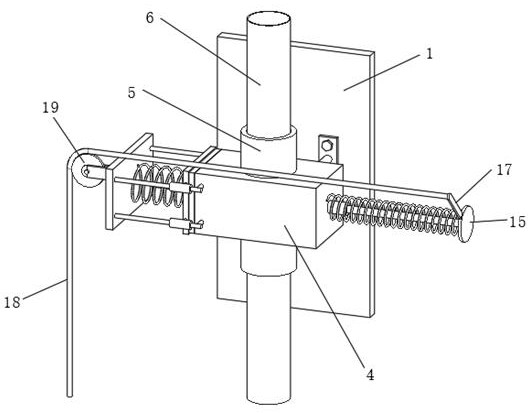
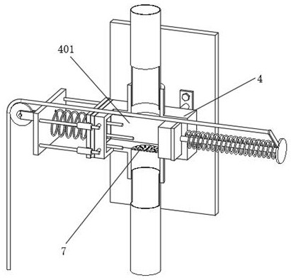
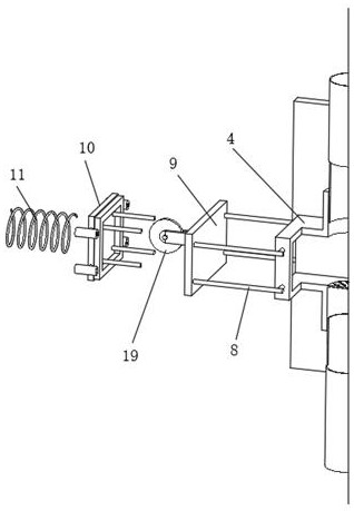
[0029] Embodiments of the present invention provide a drainage device based on roof drainage, such as Figure 1-7 As shown, including the wall main body 1, the front of the wall main body 1 is fixedly connected with an I-shaped installation plate 2 through expansion bolts, and the four corners of the I-shaped installation plate 2 are fixedly connected with a support column 3, and the support column 3 is far away from the I-shaped installation plate. One end of 2 is fixedly connected with an anti-blocking box body 4, and the inside of the anti-blocking box body 4 is provided with a box body cavity 401, and the top and bottom of the anti-blocking box body 4 are fixedly connected with a connecting pipe seat 5, and the connecting pipe seat 5 The center of the shaft is movably inserted with a mounting tube 6, the lumen of the mounting tube 6 communicates with the box body cavity 401, and the top wall and bottom wall of the box body cavity 401 are provided with circular holes corresp...

Embodiment 2

[0035] Embodiments of the present invention provide a drainage device based on roof drainage, such as Figure 1-7 As shown, including the wall main body 1, the front of the wall main body 1 is fixedly connected with an I-shaped installation plate 2 through expansion bolts, and the four corners of the I-shaped installation plate 2 are fixedly connected with a support column 3, and the support column 3 is far away from the I-shaped installation plate. One end of 2 is fixedly connected with an anti-blocking box body 4, and the inside of the anti-blocking box body 4 is provided with a box body cavity 401, and the top and bottom of the anti-blocking box body 4 are fixedly connected with a connecting pipe seat 5, and the connecting pipe seat 5 The center of the shaft is movably inserted with a mounting tube 6, the lumen of the mounting tube 6 communicates with the box body cavity 401, and the top wall and bottom wall of the box body cavity 401 are provided with circular holes corresp...

Embodiment 3

[0040] Embodiments of the present invention provide a drainage device based on roof drainage, such as Figure 1-7 As shown, including the wall main body 1, the front of the wall main body 1 is fixedly connected with an I-shaped installation plate 2 through expansion bolts, and the four corners of the I-shaped installation plate 2 are fixedly connected with a support column 3, and the support column 3 is far away from the I-shaped installation plate. One end of 2 is fixedly connected with an anti-blocking box body 4, and the inside of the anti-blocking box body 4 is provided with a box body cavity 401, and the top and bottom of the anti-blocking box body 4 are fixedly connected with a connecting pipe seat 5, and the connecting pipe seat 5 The center of the shaft is movably inserted with a mounting tube 6, the lumen of the mounting tube 6 communicates with the box body cavity 401, and the top wall and bottom wall of the box body cavity 401 are provided with circular holes corresp...


PUM


Abstract

The invention discloses a drainage device for draining water from a roof, and relates to the field of roof drainage. The drainage device for draining the water from the roof comprises a wall surface main body, an I-shaped mounting plate is fixedly connected to the front face of the wall surface main body through expansion bolts, supporting columns are fixedly connected to the four corners of the I-shaped mounting plate, anti-blocking box bodies are fixedly connected to the ends, away from the I-shaped mounting plate, of the supporting columns, and a box body cavity is formed in each anti-blocking box body; and connecting pipe seats are fixedly connected to the top and the bottom of each anti-blocking box body, a mounting pipe is movably inserted at the axis of each connecting pipe seat, and a pipe cavity of each mounting pipe is in communication with the corresponding box body cavity. According to the drainage device for draining the water from the roof, when the mounting pipes are used for draining the water from the roof, impurities may be brought into a pipeline, then drained into the anti-blocking box bodies and accumulated in the box body cavities the under the action of a filter screen plate, and when the impurities in the box body cavities need to be cleared, a circular plate is directly pushed to drain the impurities out.

Description

technical field [0001] The invention relates to the technical field of roof drainage, in particular to a drainage device based on roof drainage. Background technique [0002] The bungalows built in rural areas in some northern regions will easily leak water due to long-term waterlogging, so in daily life, it is often necessary to clean out the accumulated water on the bungalows, so corresponding drainage will be set up Outlets and drains to clean up stagnant water. [0003] However, in actual use, it is found that some impurities such as leaves may often be mixed on the roof of the building, which will enter the drain pipe through the water flow, and over time it will cause internal blockage at the bend at the bottom of the drain pipe, which will affect the drainage effect of the drain pipe, and Impurities inside the pipeline are inconvenient to discharge, which often makes the entire drainage device invalid, and the operation of dredging the pipeline is very troublesome. T...

Claims


Application Information

Patent Timeline
IPC IPC(8): E04D13/08
CPCE04D13/08E04D2013/084E04D2013/0846E04D2013/086E04D2013/0866
Inventor 胡泽尧
Owner 胡泽尧
Why Eureka
Try Eureka