Air conditioning apparatus

a technology for air conditioning and air intake, which is applied in the direction of domestic cooling apparatus, heating types, separation processes, etc., can solve the problems of increasing carbon dioxide, reducing the efficiency of air flow, so as to improve the air flow channel and minimize the effect of flow loss

Inactive Publication Date: 2007-03-22
LG ELECTRONICS INC
View PDF15 Cites 81 Cited by
  • Summary
  • Abstract
  • Description
  • Claims
  • Application Information

AI Technical Summary

Benefits of technology

[0013] A still further another object of the present invention to provide an air conditioning apparatu

Problems solved by technology

When a living thing breathes in a closed space, carbon dioxide increases with time, and thus it becomes more difficult for the living thing to breathe in the closed space.
However, since the stand-type air purifiers are placed on a floor, floating impurities such as dust cannot be effectively removed.
Further, children or babies often damage such stand-type air purifiers by falling or improperly operating the stand-typ

Method used


Image

  • Air conditioning apparatus
  • Air conditioning apparatus
  • Air conditioning apparatus

Examples


first embodiment

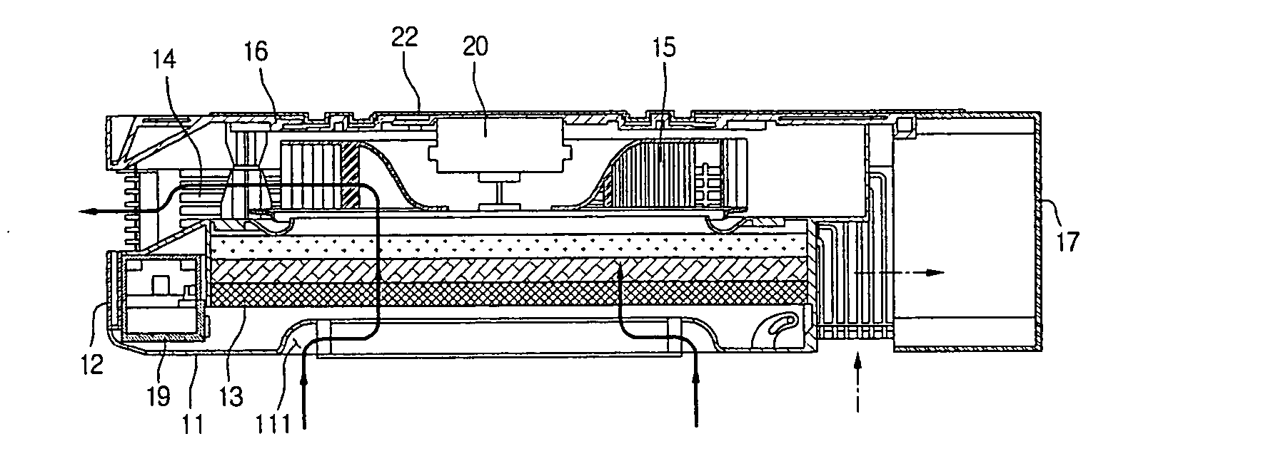
[0076]FIG. 6 is a sectional view taken along line I-I′ of FIG. 5, showing a suction panel driving structure according to the present invention.

[0077] Referring to FIG. 6, the suction panel driving structure is configured with the front cover 11, the suction panel 112 movable installed on a center portion of the front cover 11, and a driving motor M actuating the suction panel 112.

[0078] In detail, the driving motor M is connected to the suction panel 112. Preferably, the driving motor M can be rotated in both directions. The indoor air suction hole 111 is not larger than the suction panel 112 such that the indoor air suction hole 111 can be entirely closed by the suction panel 112.

[0079] When a ventilation mode is selected in this configuration, the fan 15 is driven to suck outdoor air, and the driving motor M is operated to lift the suction panel 112. That is, in the ventilation mode, the indoor air suction hole 111 is securely closed by the lifted suction panel 112. Outdoor air ...

second embodiment

[0082]FIG. 7 is a sectional view showing the suction panel driving structure according to the present invention.

[0083] Referring to FIG. 7, the suction panel driving structure is characterized by at least one suction panel 112a pivotably mounted on a front cover 11.

[0084] In detail, one end of the suction panel 112a is rotatably mounted on the front cover 11 using a hinge or the like, and a driving motor M is provided to rotate the suction panel 112a. If one suction panel 112a is mounted on the front cover 11, the suction panel 112a has the same size as an indoor air suction hole 111. Further, one end of the suction panel 112a is rotatably mounted on an edge of the indoor air suction hole 111, and the suction panel 112a is rotated forwardly and backwardly by the driving motor M.

[0085] Two or more suction panels 112a can be mounted on the front cover 11. For example, if two suction panels 112a are mounted on the front cover 11 as shown in FIG. 7, one ends of the suction panels 112a...

third embodiment

[0087]FIG. 8 is a sectional view showing the suction panel driving structure according to the present invention.

[0088] Referring to FIG. 8, the suction panel driving structure is characterized by at least one suction panel that is horizontally movable on a front cover for opening and closing an indoor air suction hole.

[0089] In detail, the suction panel driving structure is configured with a front cover 11 having an indoor air suction hole 111 in a center portion, a suction panel 112b mounted on a top surface of the front cover 11 and movable in a horizontal direction, and a driving motor M driving the suction panel 112b.

[0090] In more detail, like in the embodiment shown in FIG. 7, one or more suction panels 112b can be mounted on the front cover 11. Preferably, two suction panels 112b may be mounted on the front cover 11. Each suction panel 12b is horizontally moved by the driving motor M for opening and closing the indoor air suction hole 111. One driving motor M can drive all ...


PUM

PropertyMeasurementUnit
Fractionaaaaaaaaaa
Lengthaaaaaaaaaa
Angleaaaaaaaaaa

Abstract

An air conditioning apparatus is provided. The air conditioning apparatus includes a cover assembly having an indoor air suction hole, a filter assembly cleaning indoor air sucked through the indoor air suction hole, and a grill. The grill includes a discharge grill formed on a side for discharging the indoor air cleaned by the filter assembly to an indoor area, and an exhaust grill for discharging indoor air to an outdoor area. A fan assembly draws indoor or outdoor air toward the grill. A rear panel is coupled to the grill. The rear panel includes a suction hole formed in one side for introducing outdoor air and an exhaust hole formed beside the suction hole for discharging indoor air to the outdoor area.

Description

BACKGROUND OF THE INVENTION [0001] 1. Field of the Invention [0002] The present invention relates to an air conditioner, and more particularly, to an air conditioning apparatus that can provide both ventilation and air cleaning. [0003] 2. Description of the Related Art [0004] When a living thing breathes in a closed space, carbon dioxide increases with time, and thus it becomes more difficult for the living thing to breathe in the closed space. Therefore, closed spaces, such as an office where a lot of people works together or the interior of a car, should be periodically ventilated. A ventilation system can be generally used for this purpose. [0005] Meanwhile, air purifiers are used for removing impurities from indoor air. Most commercial air purifiers are stand-type air purifiers that are placed on a floor when in use. However, since the stand-type air purifiers are placed on a floor, floating impurities such as dust cannot be effectively removed. Further, children or babies often...

Claims


Application Information

Patent Timeline
IPC IPC(8): F24F13/06B01D46/00F25D17/04F24F7/003F24F1/035F24F8/108
CPCB01D46/0004Y02B30/78B01D46/0038B01D46/0039B01D46/008B01D2267/40B01D2273/30B01D2279/50F24F3/1603F24F11/0017F24F13/32F24F2001/0096F24F2003/1614F24F2011/0026F24F2013/0616F24F2221/14B01D46/0023F24F11/30F24F2110/50F24F2110/70F24F1/0071F24F8/108F24F8/10Y02B30/70F24F1/035B01D46/62B01D46/88F24F11/52F24F11/56F24F7/003Y02A50/20
Inventor SONG, CHANG HYUNLEE, HO BEOMPARK, JONG HOONKANG, DONG HOONKO, KANG MYUNG
Owner LG ELECTRONICS INC
Why Eureka
Try Eureka