Lancet and lancing apparatus

a technology of lancet and cap, which is applied in the field of lancet and lancet, can solve the problems of complicated and sometimes difficult detachment of the lancet body by using the cap, and achieve the effect of avoiding interference with the stopper portion

Inactive Publication Date: 2007-04-05
ARKRAY INC
View PDF4 Cites 88 Cited by
  • Summary
  • Abstract
  • Description
  • Claims
  • Application Information

AI Technical Summary

Benefits of technology

[0008] An object of the present invention is to make it possible to attach and remove a lancet by an easy operation and to dispose of a lancet hygienically.
[0025] When the casing of the lancet to be used includes a stopper portion for preventing the lancet body from dropping through a lower opening of the casing in a state in which the lancet body is movable relative to the casing, the lancing apparatus further comprises a lancet holder for holding the lancet body. For instance, the lancet holder may be movable without interfering with the stopper portion in a state in which the lancet is attached. In this instance, the lancet holder may be formed with a recess for avoiding the interference with the stopper portion.

Problems solved by technology

Moreover, the detachment of the lancet body 82 by using the cap 83 is complicated and sometimes difficult particularly for elderly people or people with weak eyesight.

Method used


Image

  • Lancet and lancing apparatus
  • Lancet and lancing apparatus
  • Lancet and lancing apparatus

Examples


first embodiment

[0074] Firstly, the present invention will be described with reference to FIGS. 1-23.

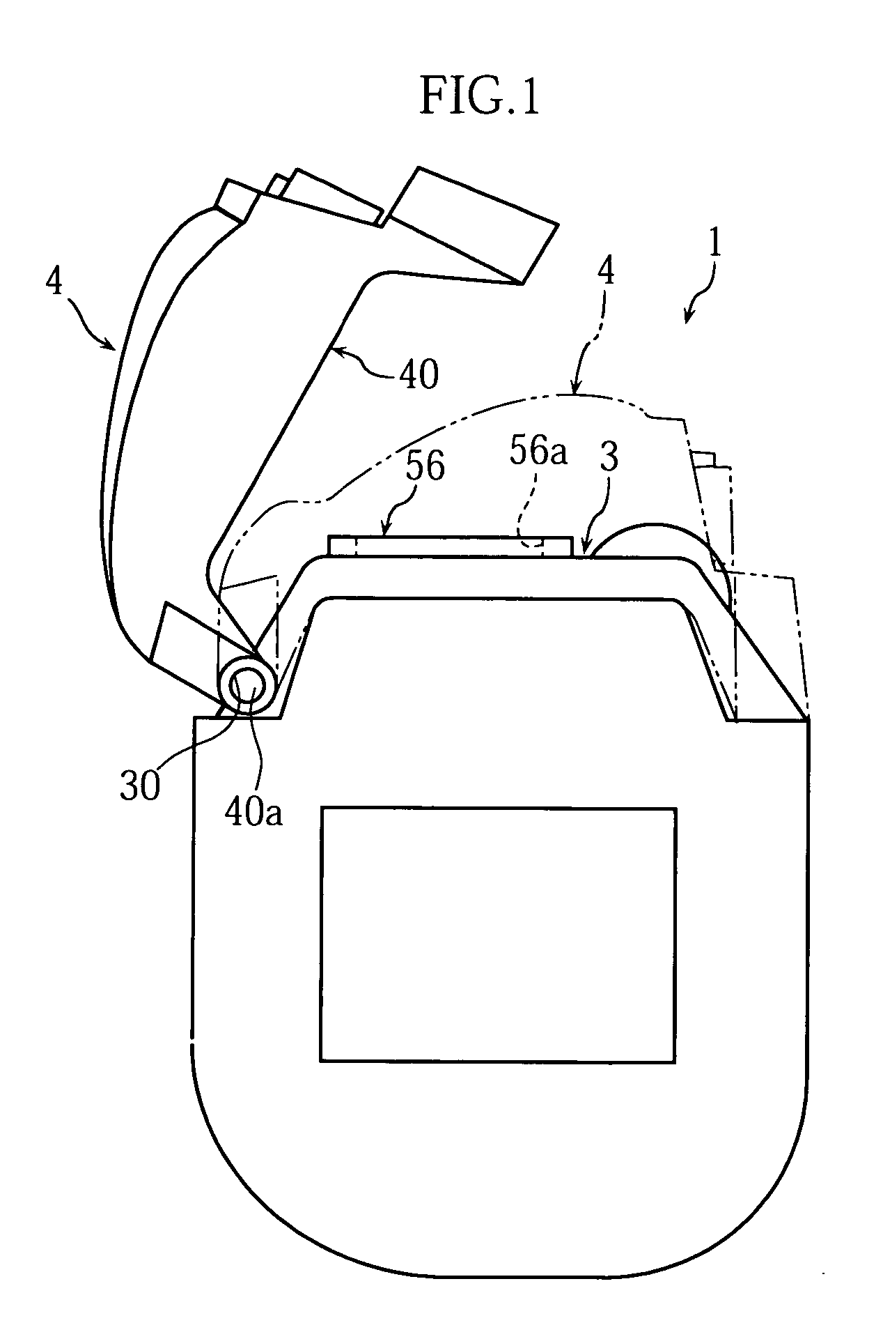
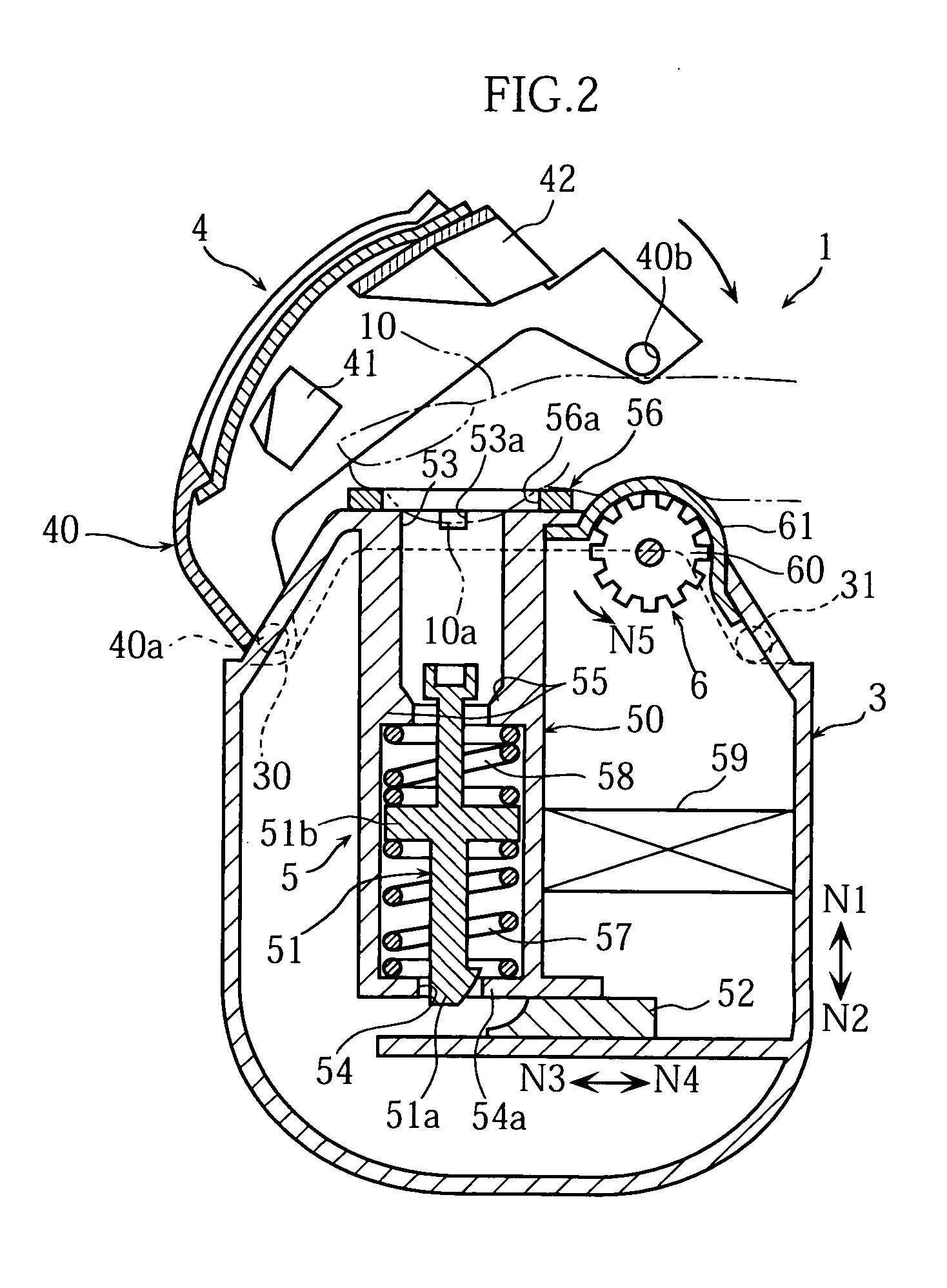
[0075]FIGS. 1-3 show a lancing apparatus 1 which is used with a lancet 2 attached thereto. The lancing apparatus includes an apparatus body 3, and a lid 4 which defines an accommodation space 11 (See FIG. 4) for inserting a fingertip 10 between the apparatus body 3 and the lid.

[0076] The apparatus body 3 includes a lancing mechanism 5 and a liquid supplying mechanism 6.

[0077] As shown in FIGS. 2 and 3, the lancing mechanism 5 serves to lance the fingertip 10 (See FIG. 4) retained in the accommodation space 11, and includes a housing 50, a lancet holder 51 and an operative portion 52.

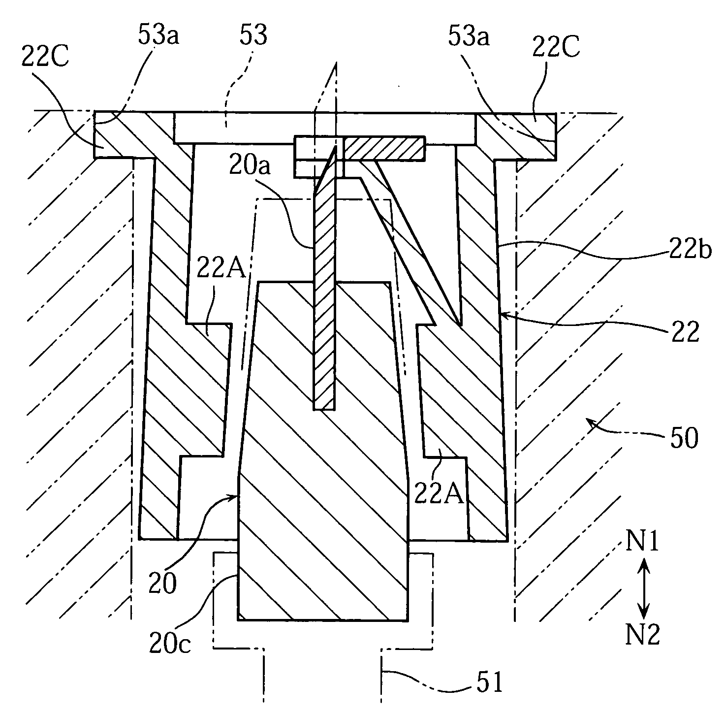
[0078] The housing 50 serves to accommodate the lancet 2 and the lancet holder 51. The housing 50 includes an opening 53, a through-hole 54 and a pair of stepped portions 55.

[0079] The opening 53, which is utilized for inserting the lancet 2, includes a cutout 53a. The cutout 53a serves to engage with a projection 22...

second embodiment

[0110] the present invention will be described below with reference to FIGS. 24-27.

[0111] Similarly to the foregoing lancet 2 (See FIGS. 9-11), the lancet 2A shown in FIGS. 24-26 includes a lancet body 20A and a casing 22A. Although the parts corresponding to the cap 21 and the biosensor 23 of the foregoing lancet 2 are not illustrated in the figures, the lancet 2A may also include a cap and a biosensor.

[0112] The casing 22A includes a slit 27A, and recesses 28A as a contact portion. The slit 27A is provided to allow the movement of a projection 50Aa provided at the housing 50A. The slit 27A comprises an arcuate cutout portion 27Aa and a linear portion 27Ab to be generally T-shaped as a whole. In the casing 22, the arcuate cutout portion 27Aa and portions on opposite sides of the linear portion 27Ab function as a leaf spring. The width of the linear portion 27Ab is smaller than the diameter of the projection 50Aa of the housing 50A so that the width can be enlarged by the projectio...

third embodiment

[0150] Although the lancet is provided with the lid in the present invention, a member corresponding to the lid of the lancet may be provided at the apparatus body of the lancing apparatus.


PUM


Abstract

The present invention relates to a lancet (2) including a lancet body (20) provided with a lancing needle (20a), and a casing (22) including a space extending throughout the casing for retaining the lancet body therein. In the lancet (2), the lancet body (20) is fixed to the casing (22) when an external force exceeding a predetermined level in a particular direction is not applied to the casing (22), whereas the lancet body (20) becomes movable relative to the casing (22) when an external force exceeding the predetermined level in the particular direction is applied to the casing (22). The present invention also relates to a lancing apparatus which is used with the lancet (2) attached thereto.

Description

TECHNICAL FIELD [0001] The present invention relates to a technique for extracting blood from a lancing target portion such as the skin. BACKGROUND ART [0002] In a conventional method for extracting blood from skin, a disposable lancet is attached to a lancing apparatus, and the lancing needle of the lancet is caused to stick into the skin by utilizing a driving mechanism of the lancing apparatus (See Patent Document 1, for example). [0003] As shown in FIGS. 43 and 44 of the present application, the lancet 8 disclosed in the Patent Document 1 comprises a lancet body 82 including a lancing needle 80 and a columnar portion 81, and a cap 83 covering the tip end of the lancing needle 80. A notch 84 is formed between the lancet body 82 and the cap 83. In the lancet 8, the lancet body 82 and the cap 83 are separable at the notch 84, as shown in FIG. 45. As clearly shown in FIG. 44, the cap 83 includes two recesses 85 and 86. The two recesses 85 and 86 communicate with each other via a thr...

Claims


Application Information

Patent Timeline
Patent Type & Authority Applications(United States)
IPC IPC(8): A61B5/00A61B17/32A61B5/15
CPCA61B5/1411A61B5/15186A61B5/150022A61B5/150213A61B5/150358A61B5/150412A61B5/150549A61B5/150618A61B5/150648A61B5/150717A61B5/150755A61B5/15113A61B5/15117A61B5/1513A61B5/1519A61B5/15194A61B5/157A61B5/151
Inventor MATSUMOTO, DAISUKEKASAI, TOKUO
Owner ARKRAY INC
Why Eureka
Try Eureka